Steel plate bending device for building

A bending device and construction technology, applied in the direction of feeding device, positioning device, storage device, etc., can solve the problems of reducing work efficiency, difficult to control the bending angle, wasting materials, etc., and achieve high work efficiency, fast and efficient The effect of bending

Inactive Publication Date: 2021-01-26
李永健
View PDF0 Cites 0 Cited by
  • Summary
  • Abstract
  • Description
  • Claims
  • Application Information

AI Technical Summary

Problems solved by technology

As an indispensable material in the construction industry, steel plates are widely used in construction projects. Because steel plates are often made into long strips for the convenience of transportation when they leave the factory, they are often made into strips according to different usage occasions and requirements. The steel plate is cut and bent, but because the material of the steel plate is relatively hard, it takes a lot of physical strength and time for the workers to beat and bend it, and the bending angle is difficult to control. If the bending angle is excessive, it needs to be folded back for reprocessing. Hammer hitting the steel plate will also leave a lot of hammer marks on the steel plate, and the steel plate will be broken if the hammer is too hard, wasting materials and greatly increasing the project cost
Therefore, in the actual use of the steel plate, it is often necessary to perform a certain bending operation on the steel plate first. Most of the existing steel plate bending methods are completed manually. Place the steel plate on the anvil, and beat the steel plate with a hammer to bend it, which is not only time-consuming and labor-intensive, but also increases the labor intensity of the workers and reduces the work efficiency; a small part relies on simple mechanical bending devices for bending. The structure of this type of device is relatively simple, and the bending accuracy is low, often requiring secondary processing during use

Method used


Image

  • Steel plate bending device for building
  • Steel plate bending device for building
  • Steel plate bending device for building

Examples


Embodiment 1

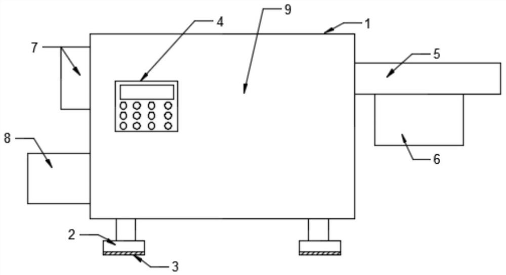
[0026] see Figure 1-6 , in an embodiment of the present invention, a steel plate bending device for construction, comprising: a box body 1, a leg 2 is fixedly installed at the bottom of the box body 1, and a power control box is arranged on a panel on one side of the box body 1 4. A stock plate 5 is fixed on one side of the box body 1, and a steel plate conveying mechanism 6 is fixed on the lower part of the stock plate 5; a steel plate cutting mechanism 7 is fixed on the other side of the box body 1, and the steel plate A material storage box 8 is fixed on the box body 1 at the lower part of the cutting mechanism 7 , and a steel plate bending mechanism 9 is arranged inside the box body 1 .

[0027] In this embodiment, the bottom of the legs 2 is provided with an anti-skid shock absorbing pad 3, which helps to reduce the vibration amplitude during the use of the device, and prevents excessive vibration amplitude from causing greater damage to the working process. influences....

Embodiment 2

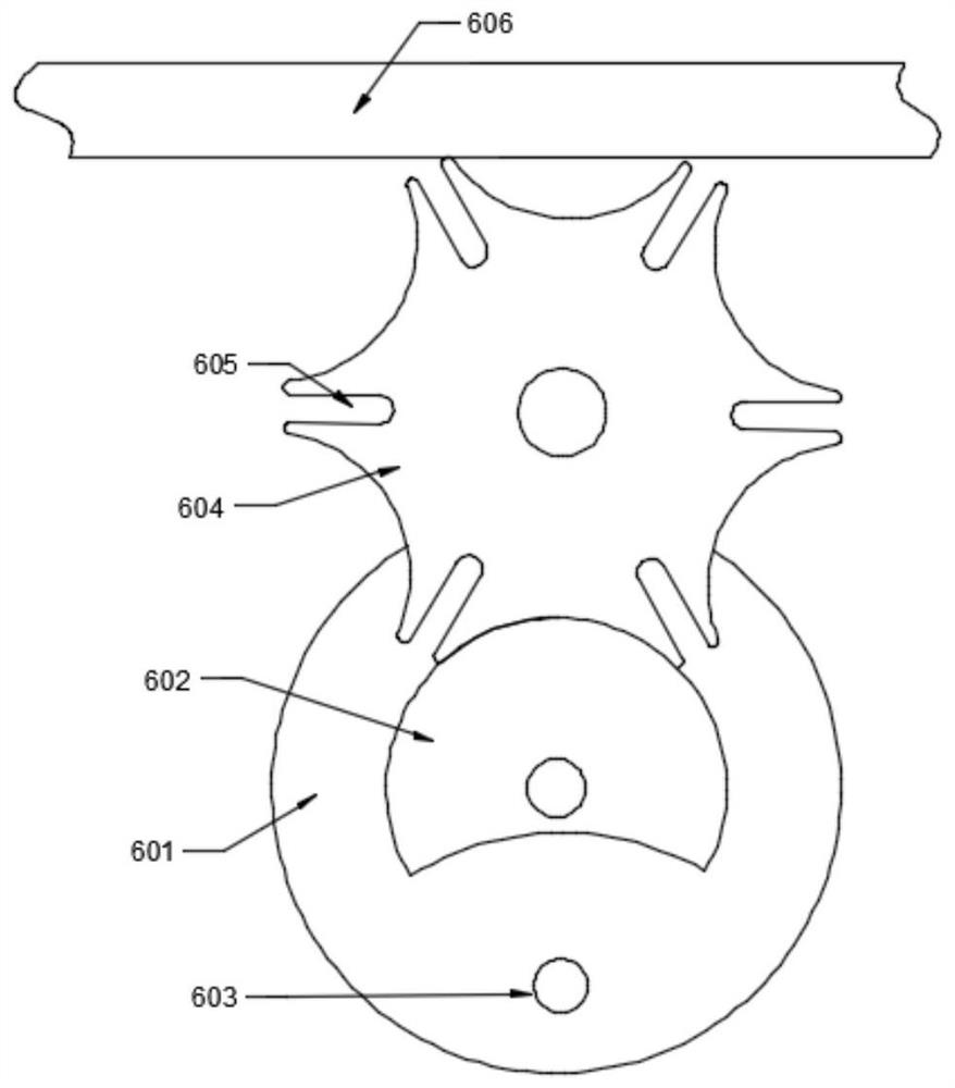
[0029] see Figure 1-6 , in this embodiment, the steel plate conveying mechanism 6 includes: a first wheel 601, an incomplete disc 602 is fixedly mounted on the first wheel 601, and a groove wheel is arranged on the upper side of the incomplete disc 602 604, the said sheave 604 is provided with a toggle groove 605, and the top of said sheave 604 is provided with a steel plate 606.

[0030] In this embodiment, a lever 603 is fixed on the first wheel 601 corresponding to the notch on the incomplete disc 602 , so that the lever 603 can move the sheave 604 conveniently.

[0031] In this embodiment, the diameter of the driving rod 603 is not larger than the groove width of the driving groove 605 , which is convenient for the driving rod 603 to enter the driving groove 605 to move the sheave 604 .

Embodiment 3

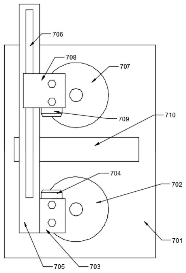
[0033] see Figure 1-6 , in this embodiment, the steel plate cutting mechanism 7 includes: a cutting bottom plate 701, a second wheel 702 is fixedly mounted on the cutting bottom 701, a first fixed block 703 is rotatably mounted on the second wheel 702, The upper part of the first fixed block 703 is fixedly equipped with a first cutter 704, and a connecting plate 705 is fixed on one side of the first fixed block 701, and a slide rail 706 is arranged on the connecting plate 705, and a slide rail 706 is arranged on the slide rail 706. A second fixed block 708 is slidably installed, and a second cutter 709 is fixed on the underside of the second fixed block 708, and a third wheel disc 707 is arranged on the rear side of the second fixed block 708 while the second fixed block 708 is rotated. A material outlet 710 is provided on the bottom plate 701 between the wheel 702 and the third wheel 707 .


PUM


Abstract

The invention relates to the technical field of building equipment, in particular to a steel plate bending device for a building. The steel plate bending device comprises a box body, wherein supporting legs are fixedly mounted on the bottom of the box body; a power supply control box is arranged on a panel at one side of the box body; a material placing plate is fixedly arranged at one side of thebox body; a steel plate conveying mechanism is fixedly arranged on the lower part of the material placing plate; a steel plate cutting mechanism is fixedly arranged at the other side of the box body;a material storage box is fixedly arranged on the box body at the lower part of the steel plate cutting mechanism; and a steel plate bending mechanism is arranged inside the box body. The device canquickly and efficiently bend the steel plate, and further can regulate a bending length according to needs during bending; and the bent steel plate can be directly collected in a unified mode for laser use after being cut, so that work efficiency is high, and thus, the steel plate bending device is safe and reliable.

Description

technical field [0001] The invention relates to the technical field of construction equipment, in particular to a steel plate bending device for construction. Background technique [0002] With the rapid development of my country's construction industry, the equipment and tools used in the construction industry are becoming more and more advanced. As an indispensable material in the construction industry, steel plates are widely used in construction projects. Because steel plates are often made into long strips for the convenience of transportation when they leave the factory, they are often made into strips according to different usage occasions and requirements. The steel plate is cut and bent, but because the material of the steel plate is relatively hard, it takes a lot of physical strength and time for the workers to beat and bend it, and the bending angle is difficult to control. If the bending angle is excessive, it needs to be folded back for reprocessing. Beating t...

Claims


Application Information

Patent Timeline
Patent Type & Authority Applications(China)
IPC IPC(8): B21D5/01B21D43/22B21D43/28
CPCB21D5/01B21D43/22B21D43/28
Inventor 李永健
Owner 李永健
Why Eureka
Try Eureka