
Pad

A front sheet, bending line technology, applied in the direction of absorbent pads, medical science, bandages, etc., can solve the problems of no open pad bending means, unable to maintain the shape, etc.

Pending Publication Date: 2018-04-06
DAIO PAPER CORP
View PDF11 Cites 0 Cited by
  • Summary
  • Abstract
  • Description
  • Claims
  • Application Information

AI Technical Summary

Problems solved by technology

[0006] However, in the proposal of Patent Document 1, the left side and the right side of the absorber folded toward the widthwise center of the absorber overlap, and therefore, the front sheet faces the widthwise center of the absorber. A large number of protrusions formed at the site may not be able to maintain the shape due to the pressing of the left and right sides of the absorber
Also, in Patent Document 2, there is no disclosure of a means for bending the pad.

Method used


Image

  • Pad
  • Pad
  • Pad

Examples


no. 2 Embodiment approach >

[0086] Next, the mat of the second embodiment will be described. In addition, the same reference numerals are assigned to the same members as those of the pad of the first embodiment, and description thereof will be omitted. Such as Figure 15 As shown, in the front-rear direction end portion of the outer absorbent body 23B, the positions facing the first left side bending line 33A and the second right side bending line 33B are provided with predetermined intervals in the width direction. The rectangular first left front overlapping portion 50A and the first right front overlapping portion 50B extend in the direction. Also, the first left front overlapping portion 50A and the first right front overlapping portion 50B can be formed by increasing the weight per unit area of ​​the fiber piling body of pulp fibers forming the outer absorbent body 23B.

[0087] A second left rear overlapped portion 51A and a second right rear overlapped portion 51B having substantially triangular...

no. 3 Embodiment approach >

[0090] Next, the mat of the third embodiment will be described. In addition, the same reference numerals are assigned to the same members as those of the pad of the first embodiment, and description thereof will be omitted. Such as Figure 16 As shown, on both sides of the width direction of the outer absorbent body 23B, there are respectively provided rectangular third fold lines extending in the front-rear direction with predetermined intervals in the width direction at the positions facing the second bending line 34 . The left middle overlapping portion 52A and the third right middle overlapping portion 52B. In addition, the front side portion of the third left middle overlapping portion 52A extends to the front side of the second bending line 34 , and the rear side portion of the third left middle overlapping portion 52A extends to the rear side of the second bending line 34 . Similarly, the front portion of the third right middle overlapping portion 52B extends to the f...


PUM


Abstract

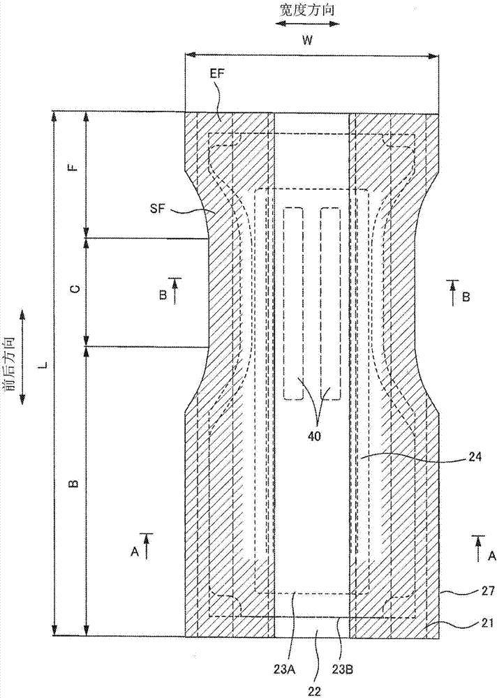
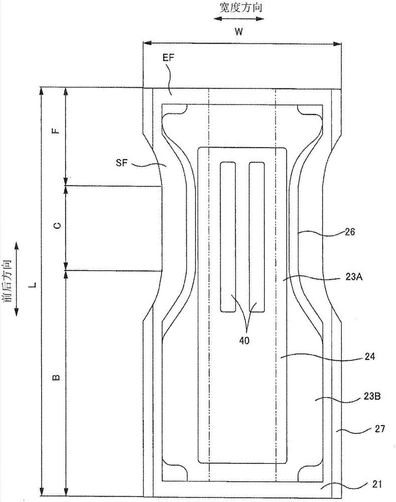
The invention provides a pad with which a thrice-folded state in a front-back direction is achieved for maintaining the shape of a large number of convexities protruding on a surface sheet that prevents a decrease in liquid diffusion performance. A solution is provided by: causing, in plan view, a left anterior section of an anterior section to extend further left than a left-side narrowing edge of a narrowest-width section of a narrowing section, and a right anterior section of the anterior section to extend further right than a right-side narrowing edge of the narrowest-width section of thenarrowing section; causing, in plan view, a left posterior section of a posterior section to extend further left than the left-side narrowing edge of the narrowest-width section of the narrowing section, and a right posterior section of the posterior section to extend further right than a right-side narrowing edge of the narrowest-width section of the narrowing section; folding the left anterior section and left posterior section inward, centered on a first left-side fold line extending in the front-back direction that is provided in proximity to a left side of the left-side narrowing edge; and folding the right anterior section and right posterior section inward, centered on a first right-side fold line extending in the front-back direction that is provided in proximity to a right side ofthe left-side narrowing edge.

Description

technical field [0001] The present invention relates to a pad attached to a belt-type disposable diaper. Specifically, it relates to a pad formed in a state folded in three in the front-rear direction in order to maintain a protrusion formed protrudingly on the top sheet. Background technique [0002] Conventionally, it has been proposed that a convex portion for improving the diffusion of excreted urine etc. is formed on the inner surface of the front sheet, and the left side of the left side of the absorber is divided into two in the width direction. The left side of the absorber is bent inward around the line, and the right side of the absorber is bent inward around the right imaginary line that divides the right side of the absorber into two in the width direction. , and then, the front side of the absorber is folded inward around the front imaginary line that divides the absorber into three in the front-rear direction, and then the rear side of the absorber is divided i...

Claims


Application Information

Patent Timeline
IPC IPC(8): A61F13/511A61F13/49
CPCA61F13/49A61F13/51104A61F2013/1556A61F2013/51355A61F2013/51186A61F2013/51078A61F13/5513A61F13/15747A61F13/53A61F13/47A61F13/15A61F13/511
Inventor 大岛彩
Owner DAIO PAPER CORP
Learn More