Building metal pile pulling and recycling device

A recovery device and technology for construction, applied in construction, sheet pile walls, foundation structure engineering, etc., can solve the problems of high labor intensity and low efficiency of metal pile recovery, so as to reduce labor intensity, improve recovery efficiency, and improve efficiency effect

Inactive Publication Date: 2021-01-26
许金梅
View PDF6 Cites 0 Cited by
  • Summary
  • Abstract
  • Description
  • Claims
  • Application Information

AI Technical Summary

Problems solved by technology

[0006] In order to overcome the shortcomings that people recycle metal piles, the metal piles are excavated by manual hand-held tools. In this way, the labor intensity of manual operation is relatively high, and the efficiency of recycling metal piles is low. The technical problem to be solved is to provide a metal pile recovery device for construction with high recovery efficiency and relatively low labor intensity of manual operation.

Method used


Image

  • Building metal pile pulling and recycling device
  • Building metal pile pulling and recycling device
  • Building metal pile pulling and recycling device

Examples


Embodiment 1

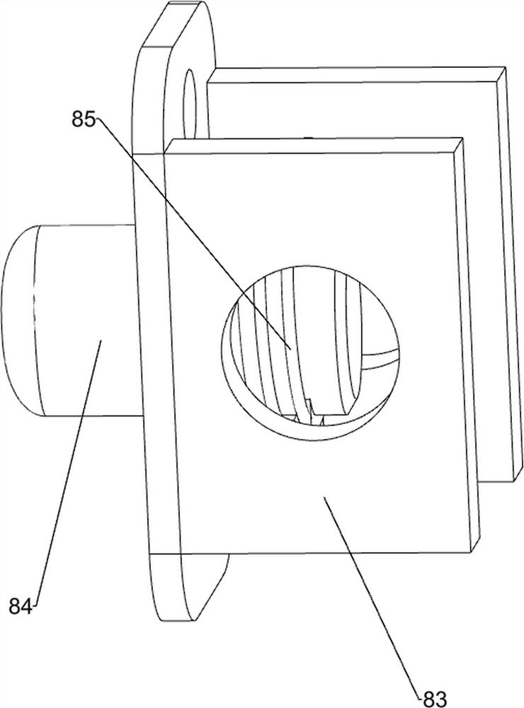
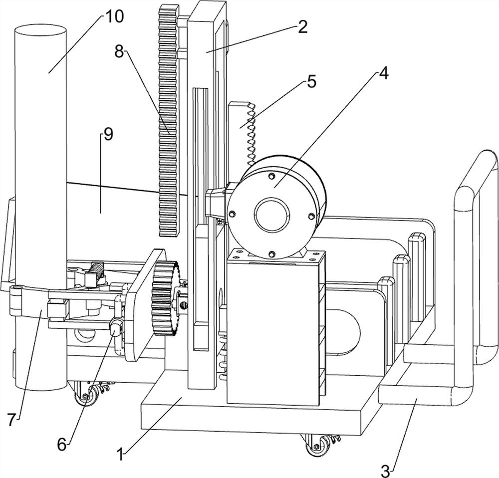
[0030] A construction metal stake pull up recovery device such as Figure 1-8 As shown, it includes a bottom plate 1, a mounting frame 2, a moving mechanism 3, a driving mechanism 4, a lifting mechanism 5, an ejection mechanism 6, a clamping mechanism 7 and a rotating mechanism 8. The left front side of the top of the bottom plate 1 is connected with the mounting frame 2, The top of the base plate 1 is connected with a drive mechanism 4, the base plate 1 is connected with a moving mechanism 3, the right side of the mounting frame 2 is connected with a lifting mechanism 5, the left side of the mounting frame 2 is connected with a rotating mechanism 8, and the left side of the rotating mechanism 8 is connected There is a clamping mechanism 7, and the left side of the clamping mechanism 7 is connected with an ejection mechanism 6.

[0031] The moving mechanism 3 includes universal wheels 31, diagonal braces 32 and push rods 33. The left and right sides of the bottom of the bottom...

Embodiment 2

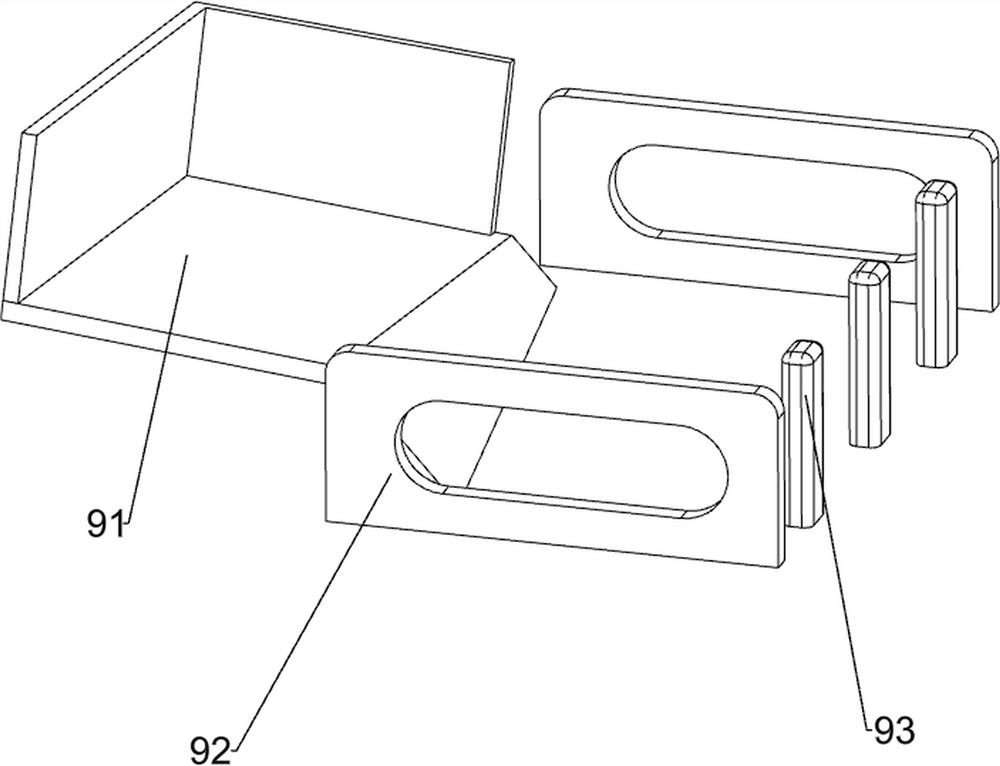
[0039] On the basis of Example 1, such as Figure 9 As shown, a discharge mechanism 9 is also included, and the discharge mechanism 9 includes a discharge plate 91, a baffle plate 92 and a block 93, and a discharge plate 91 is connected between the top of the diagonal brace 32 and the bottom plate 1, and the bottom plate 1 Both front and rear sides of the top are connected with baffles 92 , and the right rear side of the top of the bottom plate 1 is connected with multiple blocks 93 .

[0040] When people need to reclaim the metal pile 10 pulled out of the ground, under the collection effect of the discharge plate 91, the metal pile 10 detached from the fixed claw 75 falls on the discharge plate 91 thereupon, because the discharge plate 91 is Inclined design, and under the blocking effect of the baffle plate 92 and the stopper 93, the metal pile 10 will roll down to the bottom plate 1, so that people can quickly realize the collection and recovery of the metal pile 10 without ...


PUM


Abstract

The invention relates to a metal pile pulling and recycling device, in particular to a building metal pile pulling and recycling device. The technical problem to be solved by the building metal pile pulling and recycling device is to provide the building metal pile pulling and recycling device which is relatively high in metal pile recycling efficiency and relatively low in labor intensity of manual operation. In order to solve the technical problem, the invention provides the building metal pile pulling and recycling device. The device comprises a mounting frame connected with a bottom plate,a driving mechanism connected with one side, close to the mounting frame, of the bottom plate, a moving mechanism connected with one side of the bottom plate, a lifting mechanism connected with one side of the mounting frame, and a rotating mechanism connected with the other side of the mounting frame. According to the building metal pile pulling and recycling device, under the action of the moving mechanism, the driving mechanism, the lifting mechanism, an ejection mechanism, a clamping mechanism and the rotating mechanism, a metal pile can be rapidly pulled up and recycled.

Description

technical field [0001] The invention relates to a device for pulling up and recovering metal piles, in particular to a device for pulling up and recovering metal piles for construction. Background technique [0002] As the global demand for metal resources will increase significantly in the future, the world needs to reconsider the recycling of metals to reduce the negative impact on the environment. [0003] Theoretically, metals can be recycled almost unlimitedly, thus, metal recycling presents a very important opportunity for environmental protection, energy and water utilization, and contributes to the transition to a low-carbon, resource-efficient green economy, However, affected by the process and recycling costs, the metal recovery rate is still maintained at a low level. [0004] At present, when people recycle metal piles for construction, they generally use hand-held tools to excavate the metal piles. In this way, the labor intensity of manual operation is relativ...

Claims


Application Information

Patent Timeline
Patent Type & Authority Applications(China)
IPC IPC(8): E02D9/02
CPCE02D9/02
Inventor 许金梅
Owner 许金梅
Why Eureka
Try Eureka