Building foundation pit construction safety supporting structure
A support structure and foundation pit technology, applied in the field of building foundation pit construction safety support structure, can solve the problems of increased construction cost, difficulty in dismantling and recycling, and inability to use multiple times, so as to improve strength, avoid deformation or even breakage, and design novel effect
- Summary
- Abstract
- Description
- Claims
- Application Information
AI Technical Summary
Problems solved by technology
Method used
Image
Examples
Embodiment 1
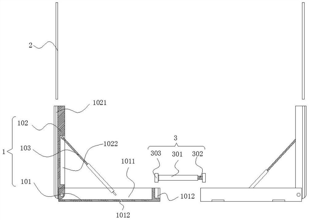
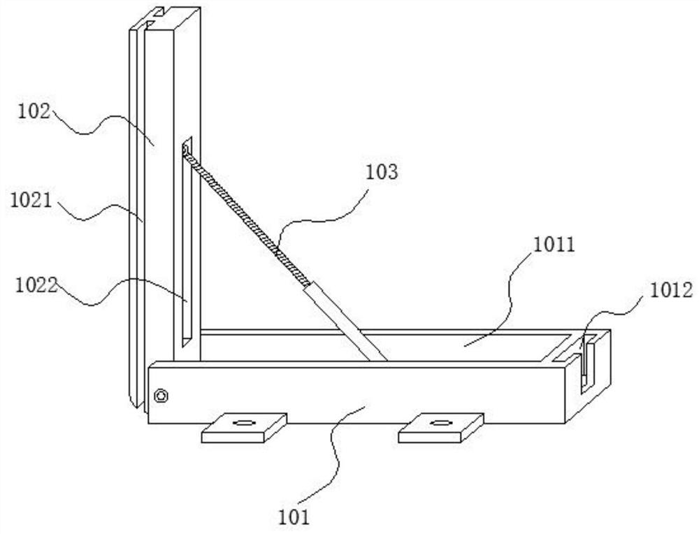
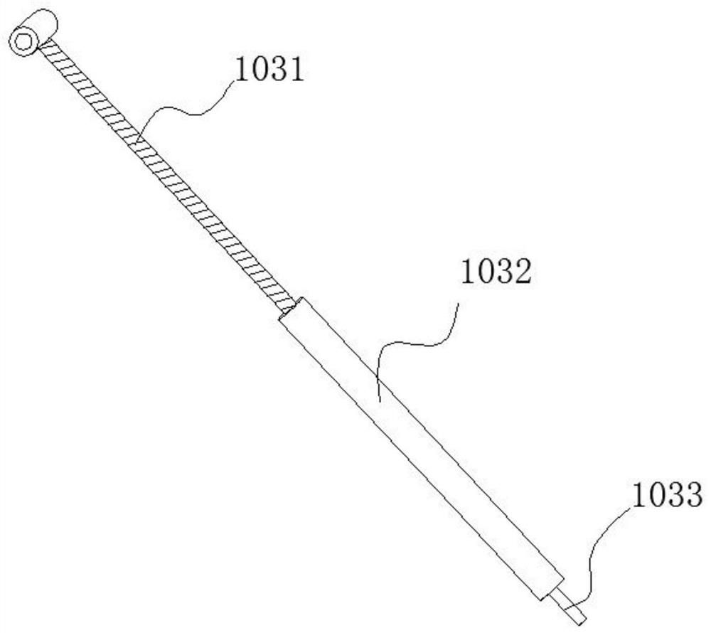
[0030] refer to Figure 1-4 , this embodiment includes a folding bracket 1, a support plate 2 and a telescopic reinforcing rod 3, the folding bracket 1 includes a bottom strut 101, a longitudinal strut 102 and a diagonal strut 103, and the bottom strut 101 and the longitudinal strut 102 rotate through a rotating shaft Connect to fold and unfold, one end of the telescopic reinforcing rod 3 is rotationally connected with the longitudinal strut 102, when the bottom strut 101 and the longitudinal strut 102 are unfolded at 90 degrees, the diagonal strut 103 is rotated out and the other end is stretched and clamped on the The support force is formed between the bottom support rod 101 and the longitudinal support rod 102 on the bottom support rod 101. Both sides of the bottom support rod 101 are fixedly provided with mounting ears. The pit foundation is supported, and one end of two corresponding folding brackets 1 close to each other is supported and fixed by the telescopic reinforc...
Embodiment 2
[0038] refer to Figure 1-5 The difference between this embodiment and the first embodiment is that a telescopic reinforcing rod 3 is added. The telescopic reinforcing rod 3 includes an adjusting rod 301, a telescopic screw rod 302 and a limit block 303. The telescoping screw 302 is inserted into the threaded slot hole and threadedly connected with the adjusting rod 301. The ends of the adjusting rod 301 and the telescopic screw 302 are connected to the limiting block 303, and the adjusting rod 301 is connected to the limiting block 303 in rotation. The telescopic screw 302 is connected to the limiting The block 303 is fixedly connected, and the end of the bottom pole 101 away from the U-shaped groove 1011 is provided with a T-shaped limiting groove 1012, and the limiting blocks 303 at both ends of the telescopic reinforcing rod 3 are respectively snapped into two correspondingly installed folding brackets 1. Inside the T-shaped limiting slot 1012.
[0039] The limit blocks 3...
Embodiment 3
[0041] refer to Figure 6-8 The difference between this embodiment and Embodiment 1 and Embodiment 2 is that it also includes a lateral support assembly, the lateral support assembly includes a rotating cross bar 1024 and a rotating cross bar 2 1026, and both sides of the longitudinal support rod 102 are provided with rotating slots 1023, the lower ends of the first rotating cross bar 1024 and the second rotating cross bar 1026 are respectively rotated and installed in the rotating grooves 1023 on both sides of the longitudinal strut 102. There is a fixed screw hole on the top, and the upper end of the rotating cross bar 1026 is provided with a docking groove 1027, and the docking groove 1027 is provided with a fixing bolt 1028, and the rotating cross bar 1024 and the rotating cross bar 2 1026 are rotated out of the rotating groove, and the adjacent rotation The plug-in block 1025 at the end of the first cross bar 1024 is inserted into the docking groove 1027 at the end of the...
PUM
 Abstract
Description
Claims
Application Information
 - R&D
- Intellectual Property
- Life Sciences
- Materials
- Tech Scout
- Unparalleled Data Quality
- Higher Quality Content
- 60% Fewer Hallucinations
Browse by: Latest US Patents, China's latest patents, Technical Efficacy Thesaurus, Application Domain, Technology Topic, Popular Technical Reports.
© 2025 PatSnap. All rights reserved.Legal|Privacy policy|Modern Slavery Act Transparency Statement|Sitemap|About US| Contact US: help@patsnap.com


