Photoelectric encoder

A technology of photoelectric encoder and photoelectric transceiver, which is applied in the field of encoder, can solve the problems of inability to produce crisp sound, unfavorable normal use, high cost investment, etc., and achieve the effects of crisp hand feeling and sound, good perception and long service life

Pending Publication Date: 2021-01-26
SOUNDWELL ELECTRONICS PROD GUANGDONG
View PDF0 Cites 0 Cited by
  • Summary
  • Abstract
  • Description
  • Claims
  • Application Information

AI Technical Summary

Problems solved by technology

[0003] At present, in some electronic products, such as car audio, car air conditioners, multimedia products, etc., the encoders used to realize functions such as volume control and function switching are generally shaft-type encoders. However, the existing shaft-type encoders on the market Most of the encoders adopt the structure of mechanical principle, that is, the signal is generated by the cooperation of the metal contact brush and the metal contact piece. This structure inevitably has the disadvantages of short service life and easy to generate cluttered signals, which is not conducive to normal use. , and will also lead to high cost input
In addition, because the positioning feel of the existing shaft-shank encoder is produced by vertically pressing the metal shrapnel on the plastic positioning point, the torque is relatively weak, and the feel of crisp sound cannot be produced.

Method used


Image

  • Photoelectric encoder
  • Photoelectric encoder
  • Photoelectric encoder

Examples


Embodiment 1

[0041] In view of the defects of the existing encoders mentioned above, the applicant actively researches and innovates on the basis of years of rich practical experience and professional knowledge in the design and manufacture of such products, and cooperates with the application of academic principles, in the hope of creating a solution that can solve the existing problems. The defect-free technology makes the encoder more practical. Through continuous research, design, and after repeated trial samples and improvements, the present invention with practical value is finally created.

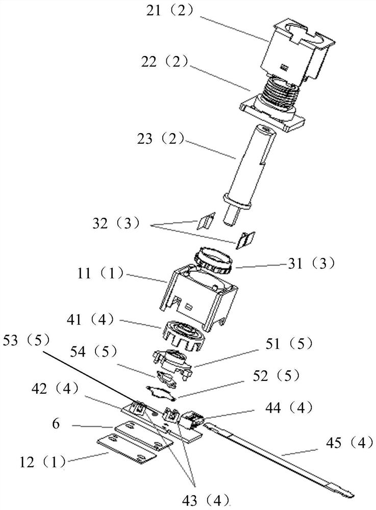
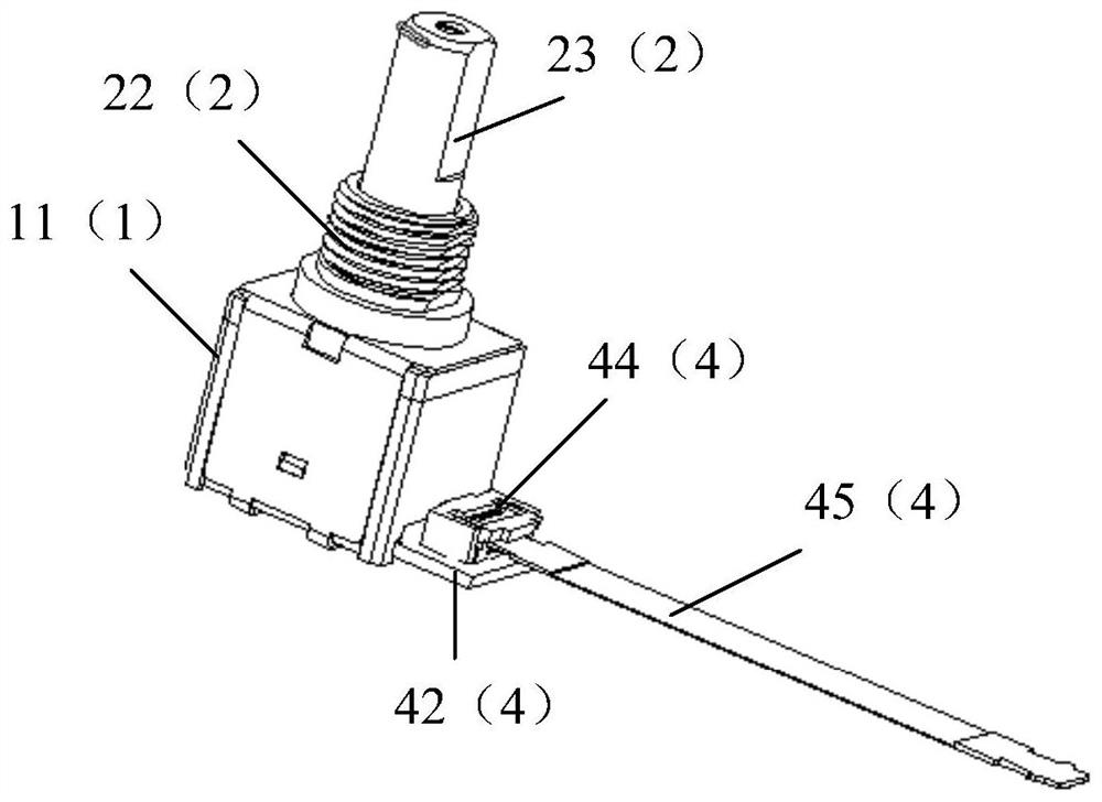
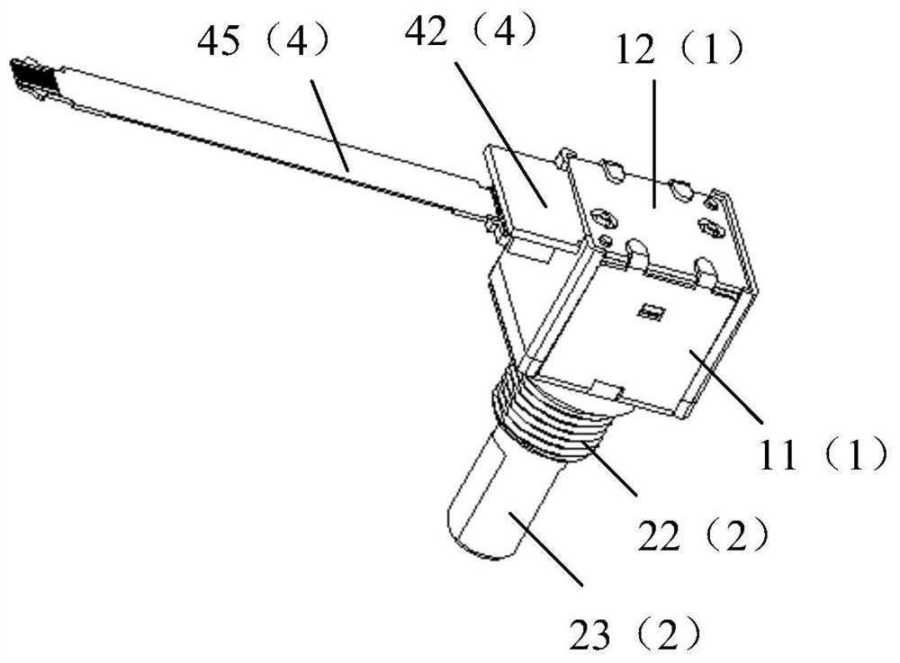
[0042] Please refer to Figure 1~3 , the embodiment of the present invention provides a photoelectric encoder, including a housing 1, a shaft core assembly 2 passing through the housing 1, and a rotating assembly 3 and a sensor assembly 4 arranged in the housing 1; wherein,

[0043] The shaft core assembly 2 includes a bracket 21, a shaft sleeve 22, and a shaft core 23; the inside of the bracke...


PUM


Abstract

The invention discloses a photoelectric encoder, which comprises a shell, a shaft core assembly, a rotating assembly and a sensor assembly, wherein the shaft core assembly comprises a support, a shaftsleeve and a shaft core; the shaft sleeve is arranged on the outer surface of the shaft core in a sleeving manner and penetrates through an opening cavity in the support; the sensor assembly comprises an anti-dazzling screen, a PCB and photoelectric transceivers; the anti-dazzling screen is arranged on the PCB and arranged on the outer surface of the shaft core in a sleeving mode, and the photoelectric transceivers are arranged on the PCB and arranged on the two sides of the anti-dazzling screen; the PCB is also provided with a connector, and the connector penetrates through the shell and isconnected with a connecting wire; the rotating assembly comprises a fluctuation disc and a rotating elastic piece; and the outer surface of the shaft core is sleeved with the fluctuation disc, and therotating elastic piece is arranged on the side face of the fluctuation disc and makes contact with the fluctuation disc in a movable fit mode to form gear positioning contact. Due to the fact that the principle of signal generation is a photoelectric type, the service life is long; and meanwhile, the positioning hand feeling mode is changed into the mode that the rotating elastic piece makes contact with the side face of the fluctuation disc, large torque can be generated, and the sensing of an operator is facilitated.

Description

technical field [0001] The invention relates to the technical field of encoders, in particular to a photoelectric encoder. Background technique [0002] Encoders are widely used in various fields. They are devices that compile and convert signals or data into signal forms that can be used for communication, transmission and storage. [0003] At present, in some electronic products, such as car audio, car air conditioners, multimedia products, etc., the encoders used to realize functions such as volume control and function switching are generally shaft-type encoders. However, the existing shaft-type encoders on the market Most of the encoders adopt the structure of mechanical principle, that is, the signal is generated by the cooperation of the metal contact brush and the metal contact piece. This structure inevitably has the disadvantages of short service life and easy to generate cluttered signals, which is not conducive to normal use. , and will also lead to high cost inp...

Claims


Application Information

Patent Timeline
Patent Type & Authority Applications(China)
IPC IPC(8): G01D5/26G01D11/24G01D11/30
CPCG01D5/26G01D11/24G01D11/30
Inventor 洪金镳苏朝晖欧阳昌雄黄家川
Owner SOUNDWELL ELECTRONICS PROD GUANGDONG
Why Eureka
Try Eureka