Balancing device for transmission shaft bracket of rolling mill

A technology of balancing device and transmission shaft, which is applied to the driving device of metal rolling mill, metal rolling, metal rolling, etc., which can solve the problem of undurable balancing device, and achieve easy maintenance, reduced swing, and no risk of breakage Effect

Inactive Publication Date: 2021-07-13
广西钢铁集团有限公司 +1
View PDF9 Cites 0 Cited by
  • Summary
  • Abstract
  • Description
  • Claims
  • Application Information

AI Technical Summary

Problems solved by technology

[0004] The purpose of the present invention is to provide a balancing device for the drive shaft bracket of a rolling mill, which can solve the problem that the balance device for the drive shaft bracket of the existing rolling mill is not durable

Method used


Image

  • Balancing device for transmission shaft bracket of rolling mill
  • Balancing device for transmission shaft bracket of rolling mill
  • Balancing device for transmission shaft bracket of rolling mill

Examples


Embodiment Construction

[0023] The present invention will be described in further detail below in conjunction with accompanying drawing embodiment:

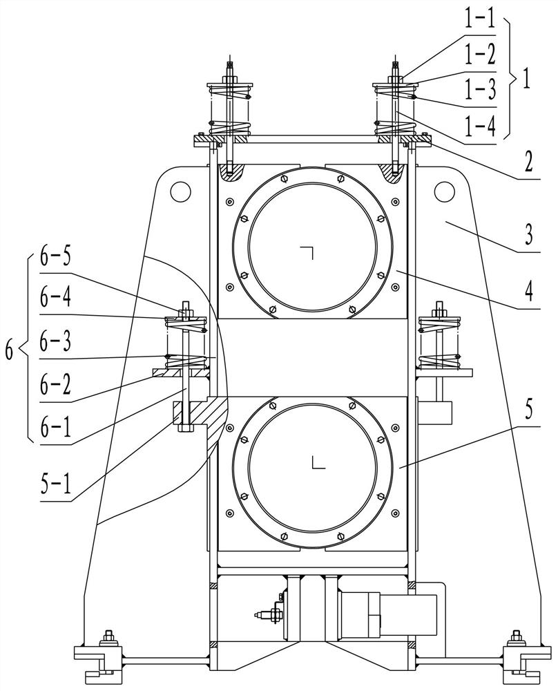
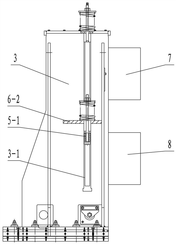
[0024] figure 1 and figure 2 The balance device of the drive shaft bracket of the rolling mill shown is composed of an upper balance unit and a lower balance unit. The upper balance unit and the lower balance unit are independent of each other. Adjusting the height position and elastic balance state of the rolling mill can better balance the self-gravity of the drive shaft of the rolling mill and the vibration generated during the rolling process. The upper bearing housing 4 for supporting the transmission shaft 7 on the rolling mill and the lower bearing housing 5 for supporting the lower transmission shaft 8 can only slide up and down in the transmission shaft bracket 3, and the two side walls of the transmission shaft bracket 3 are provided with The guide groove 3-1 matching the guide structures on both sides of the upper bearing seat 4 and the lo...


PUM


Abstract

The invention discloses a balancing device for a transmission shaft bracket of a rolling mill, and relates to the technical field of rolling equipment. The balancing device is composed of an upper balancing unit and a lower balancing unit which are mutually independent, the upper balancing unit comprises an upper fixing plate and at least two groups of upper balancing assemblies, the upper fixing plate is mounted at the top end of the transmission shaft bracket, and each upper balancing assembly comprises a double-end lead screw, an upper elastic supporting piece and an upper adjusting nut; and the lower balancing unit comprises at least two groups of lower balancing assemblies and connecting blocks which are respectively arranged on the two sides of the transmission shaft bracket, each lower balancing assembly comprises a single-head screw rod, a lower elastic supporting piece, a lower adjusting nut and a lower fixing plate, the connecting blocks are fixed on the side surface of a lower bearing seat, the lower fixing plates are horizontally fixed on the outer wall of the transmission shaft bracket, the single-head lead screws penetrate through the connecting blocks and the lower fixing plates to be in threaded connection with the lower adjusting nuts, and the lower elastic supporting pieces are supported between the lower adjusting nuts and the lower fixing plates. The balancing device solves the problem that an existing balancing device of the transmission shaft bracket of the rolling mill is not durable.

Description

technical field [0001] The invention relates to the technical field of rolling equipment, in particular to a balancing device for a transmission shaft bracket of a rolling mill. Background technique [0002] The rolling mill of the rolling system in the metallurgical industry mainly transmits torque through the universal joint shaft. Due to the length and weight of the universal joint shaft, it is necessary to design a supporting bracket to effectively support and position the universal joint shaft. A good bracket can ensure the universal joint shaft. The swing is small when turning to the drive shaft, and the up and down displacement of the universal drive shaft is small when the rolling mill is replaced and disengaged. Most universal joint shaft brackets in the industry adopt the self-weight balance mechanism of the tie rod and the self-weight balance mechanism of the chain. [0003] Due to the harsh environment of the steel rolling production line and the large operating...

Claims


Application Information

Patent Timeline
Patent Type & Authority Applications(China)
IPC IPC(8): B21B35/14
CPCB21B35/148
Inventor 吕柳新梁世顶周斌彭正刚罗卿孔令涛潘建强季永宽何伟勇高春唐茂林
Owner 广西钢铁集团有限公司
Why Eureka
Try Eureka