Concrete slump detection device and manufacturing operation method thereof

A technology for detection devices and manufacturing methods, which is applied in the direction of measuring devices, preparation of test samples, material inspection products, etc., which can solve the problem that the stability and accuracy of the slump test need to be improved, the verticality cannot be guaranteed, and the test efficiency is reduced. problem, to achieve the effect of simple structure, reducing error and improving test efficiency

Inactive Publication Date: 2021-01-26
四川兴城港瑞建材有限公司
View PDF11 Cites 4 Cited by
  • Summary
  • Abstract
  • Description
  • Claims
  • Application Information

AI Technical Summary

Problems solved by technology

The existing slump test method mainly adopts the single bucket test. During the test process, the method of vibrating the concrete with a tamping rod is generally used, and the test needs to be repeated many times to reduce the error of the test data. However, during the test process, at least there will be The following problems: the verticality of the slump test bucket cannot be guaranteed during the lifting process, and the lifting operation is completely controlled by personnel. Different groups of tests are likely to cause large experimental errors, and it will affect the personnel's ability to move into the bucket during the concrete vibration process. Add concrete, thereby delaying the test process and reducing the test efficiency
[0004] In summary, the existing concrete slump test method will cause large test errors due to artificial factors, and the stability and accuracy of the slump test need to be improved

Method used


Image

  • Concrete slump detection device and manufacturing operation method thereof
  • Concrete slump detection device and manufacturing operation method thereof
  • Concrete slump detection device and manufacturing operation method thereof

Examples


Embodiment Construction

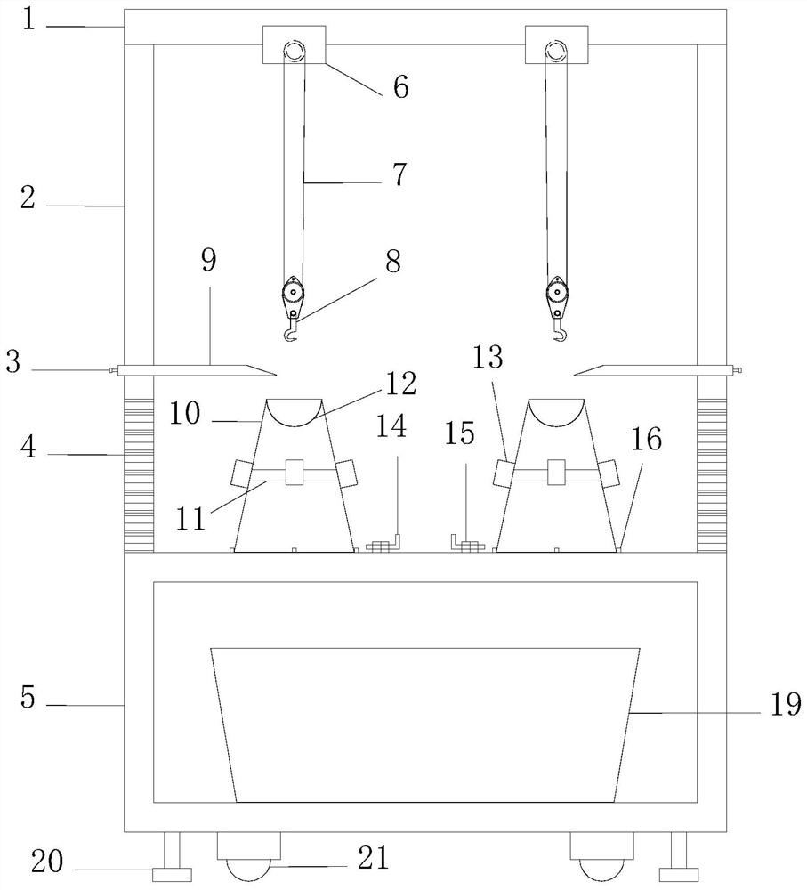
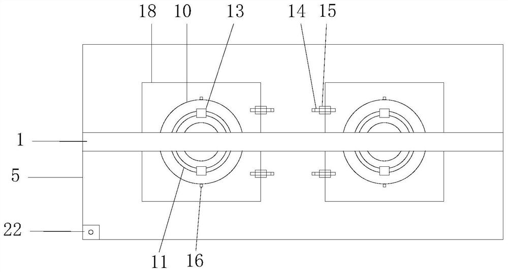
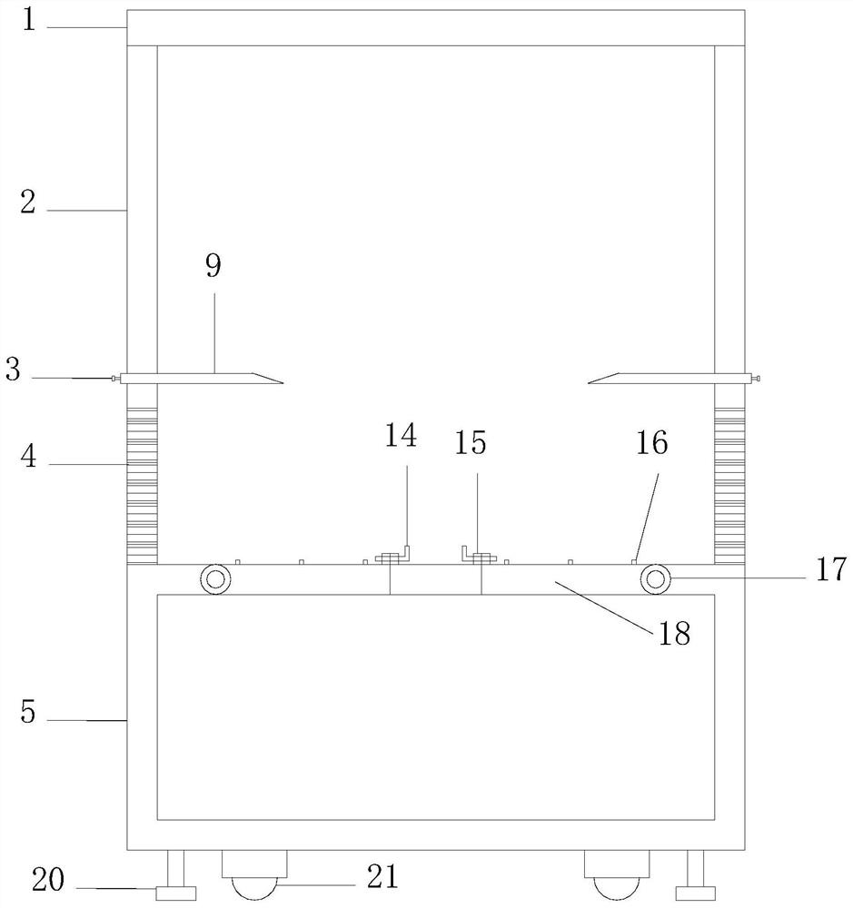
[0023] The following will clearly and completely describe the technical solutions in the embodiments of the present invention with reference to the accompanying drawings in the embodiments of the present invention. Obviously, the described embodiments are only some, not all, embodiments of the present invention. All other embodiments obtained by persons of ordinary skill in the art based on the embodiments of the present invention belong to the protection scope of the present invention.

[0024] Those skilled in the art should understand that in the disclosure of the present invention, the terms "vertical", "transverse", "upper", "lower", "front", "rear", "left", "right", " The orientation or positional relationship indicated by "vertical", "horizontal", "top", "bottom", "inner", "outer", etc. is based on the orientation or positional relationship shown in the drawings, which are only for the convenience of describing the present invention and The above terms should not be con...


PUM


Abstract

The invention provides a concrete slump detection device and a manufacturing operation method thereof. The operation method comprises the following steps that a movable plate and a detection table aretemporarily fastened through L-shaped plug pins, the detection table is adjusted to be in a horizontal state, the inner side of a test barrel is oiled and placed on the movable plate, and the test barrel is filled with mixed concrete; in the filling process, the vibrator on the test barrel is started, vibration is conducted while filling is conducted till the test barrel is full, concrete at theopening of the test barrel is flattened, the test barrel is lifted till the bottom of the test barrel is completely separated from the top end of the concrete to be detected, and the slump of the concrete to be detected is obtained through the scale marks on the stand column. The device is simple, synchronous detection can be realized, and the test efficiency is high; and errors are small, and waste materials are easy to collect.

Description

technical field [0001] The invention relates to the field of concrete detection, in particular to a concrete slump detection device and a manufacturing operation method. Background technique [0002] Concrete slump will be affected by various conditions such as the structural section of the building, steel bar content, transportation distance, pouring method, transportation mode, vibration capacity and climate, so quantitative indicators are needed to measure the degree of concrete slump. In order to judge whether the subsequent construction work can be carried out normally, the concrete slump must be tested during the concrete construction process. [0003] Slump is the measurement method and index of concrete workability. In construction sites and laboratories, slump tests are usually used to measure the fluidity of the mixture, and to evaluate its cohesion and water retention with intuitive experience. , and then get the slump of concrete. The existing slump test method...

Claims


Application Information

Patent Timeline
Patent Type & Authority Applications(China)
IPC IPC(8): G01N33/38G01N1/28
CPCG01N33/383G01N1/286
Inventor 夏开飞李岳邱燕飞阳欢蔡关虎
Owner 四川兴城港瑞建材有限公司
Why Eureka
Try Eureka