
Lens wiping device for glasses

A technology for lenses and glasses, applied in the field of lens cleaning, can solve problems such as reducing work efficiency, wasting water resources, and wasting a lot of time, and achieves the effects of improving efficiency, saving time, and being easy to take out.

Inactive Publication Date: 2021-01-26
湘潭市爱众眼镜有限公司
View PDF0 Cites 0 Cited by
  • Summary
  • Abstract
  • Description
  • Claims
  • Application Information

AI Technical Summary

Problems solved by technology

At present, due to the large batch of lenses in the optical shop, it takes a lot of time to wipe the lenses by employees, which reduces work efficiency. At the same time, the water after cleaning is directly discharged, which seriously wastes water resources.

Method used


Image

  • Lens wiping device for glasses
  • Lens wiping device for glasses
  • Lens wiping device for glasses

Examples


Embodiment 1

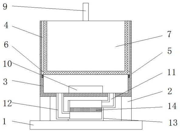
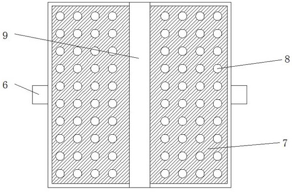
[0019] Embodiment 1, with reference to Figure 1-2 , a lens wiping device for spectacles, comprising a base 1, a column 2 is welded on both sides of the top of the base 1, and a shell 3 is welded on the top of the column 2, the inner walls of both sides of the shell 3 are provided with chute 4, and the sliding The bottom of the groove 4 is welded with a limit block 5, and the slider 6 is slidably connected in the chute 4, and the placement frame 7 is welded between the sliders 6, and the bottom of the placement frame 7 is opened with equidistant distribution. There is a water hole 8, and a handle 9 is welded on the top of the placement frame 7, an ultrasonic vibrator 10 is provided on the inner wall of the bottom of the housing 3, the liquid contained in the inner wall of the housing 3 is pure water, and the outer diameter of the placement frame 7 is the same as The inner diameter of the housing 3 is compatible, the placement frame 7 forms a sliding fit with the housing 3, the...

Embodiment 2

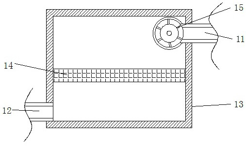
[0020] Embodiment 2, with reference to figure 1 with image 3 , a lens wiping device for glasses, comprising a casing 3, a water inlet pipe 11 is welded through one side of the bottom of the casing 3, and a water outlet pipe 12 is welded through and welded on the other side of the bottom of the casing 3, the water inlet pipe 11 and the water outlet pipe 12 A water storage tank 13 is welded between the clips, and a screen 14 is welded between the inner walls of the two sides of the water storage tank 13. One end of the water inlet pipe 12 is connected to a water pump 15, and the ultrasonic vibrator 10 communicates with the outside world through wires. The power supply is connected, and the water pump 15 is connected with the external power supply through wires, the height of the connection position between the water inlet pipe 11 and the water storage tank 13 is greater than the height of the connection position between the water outlet pipe 12 and the water storage tank 13, an...


PUM


Abstract

The invention discloses a lens wiping device for glasses, which comprises a base, wherein stand columns are welded to the two sides of the top of the base, a shell is welded to the top of the stand columns, sliding grooves are formed in the inner walls of the two sides of the shell correspondingly, limiting blocks are welded to the bottom of the sliding grooves correspondingly, sliding blocks areslidably connected into the sliding grooves correspondingly, a placement frame is welded between the sliding blocks in a butt clamping mode, water through holes distributed at equal intervals are formed in the bottom of the placement frame in a penetrating mode, a handle is welded to the top of the placement frame, an ultrasonic vibrator is arranged on the inner wall of the bottom of the shell, awater inlet pipe is welded to one side of the bottom of the shell in a penetrating mode, and a water outlet pipe is welded to the other side of the bottom of the shell in a penetrating mode. Accordingto the invention, the sliding block is arranged to be in sliding fit with the shell, purified water is contained in the shell, lenses are placed in the placement frame, then the ultrasonic vibrator enables the water to vibrate, the function of cleaning and wiping the lenses in batches is achieved, and the handle is welded to the top of the placement frame, so that the staff can take out the lenses conveniently, and time is saved.

Description

technical field [0001] The invention relates to the technical field of lens cleaning, in particular to a lens wiping device for glasses. Background technique [0002] Spectacles are items made to correct vision or protect eyes, generally including a frame and lenses, and according to whether a frame is provided on the frame, the frame can be divided into a framed frame and a frameless frame. In order to keep the eyes comfortable and clear in use, it is often necessary to wipe the eyeglasses with a spectacle cloth to ensure the wearer's good vision. At present, due to the large batch of lenses in the optical shop, it takes a lot of time to wipe the lenses by employees, which reduces work efficiency. At the same time, the water after cleaning is directly discharged, which seriously wastes water resources. Contents of the invention [0003] The purpose of the present invention is to solve the shortcomings in the prior art, and propose a lens wiping device for spectacles. ...

Claims


Application Information

Patent Timeline
Patent Type & Authority Applications(China)
IPC IPC(8): G02C13/00
CPCG02C13/006
Inventor 刘瑾
Owner 湘潭市爱众眼镜有限公司
Learn More