Power switching circuit, power switching method, wire controller and air conditioning equipment
A technology for power switching and wire controllers, which is applied in the fields of power switching methods, power switching circuits, wire controllers and air-conditioning equipment. The effect of improving stability
- Summary
- Abstract
- Description
- Claims
- Application Information
AI Technical Summary
Problems solved by technology
Method used
Image
Examples
Embodiment 1
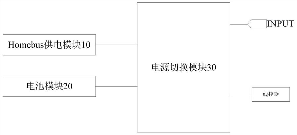
[0047] This embodiment provides a power switching circuit, figure 1 It is a structural diagram of a power switching circuit according to an embodiment of the present invention, such as figure 1 As shown, the circuit includes:
[0048] The Homebus power supply module 10 and the battery module 20 alternatively conduct with the wire controller through the power switching module 30 to supply power for the wire controller;
[0049] It also includes a power switch module 30, one end of the power switch module 30 is connected to the Homebus power supply module 10 and the battery module 20, and the other end is connected to the wire controller for controlling the first current and the second current when the preset conditions are met. The battery module is connected to the wire controller; when the first current and the second current do not meet the preset conditions, the Homebus power supply module is controlled to be connected to the wire controller; wherein, the Homebus power sup...
Embodiment 2
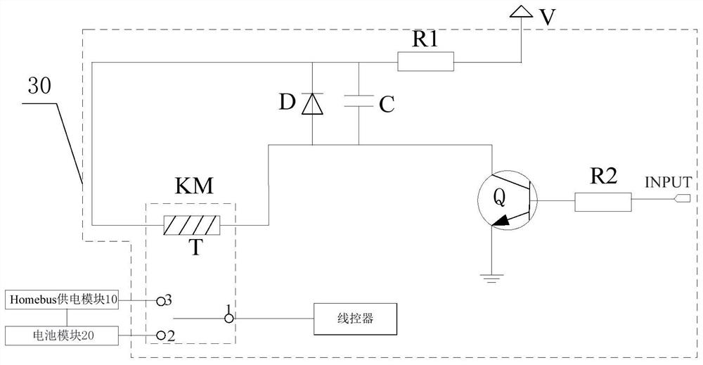
[0054] This embodiment provides another power switching circuit, figure 2 It is a structural diagram of a power switching circuit according to another embodiment of the present invention, in order to accurately control the timing of turning on the battery module or the Homebus power supply module, as figure 2 As shown, the power switching circuit includes:
[0055] Switch Q, the control terminal of the switch Q is connected to the signal input terminal INPUT, its input terminal is connected to the first terminal of the coil of the relay, and its output terminal is grounded. At least one of the two currents is greater than the preset threshold, so that the above NAND gate circuit is turned on when outputting a high-level signal; the first current output by the Homebus power supply module 10 and the second current output by the battery module 20 are less than The threshold is preset so that the above-mentioned NAND gate circuit is turned off when outputting a low-level signal...
Embodiment 3
[0062] This embodiment provides a power switching method, which is applied to the above power switching circuit, image 3 It is a flowchart of a power switching method according to an embodiment of the present invention, the method includes:
[0063] S101. Detect the first current output by the Homebus power supply module and the second current output by the battery module.
[0064] During specific implementation, the first current detected by the Homebus power supply module 10 is detected by the first ADC detection circuit, the second current output by the battery module 20 is detected by the second ADC detection circuit, and the corresponding logic level is output, when the detected current >When the preset threshold is reached, output a high level "1", when the detection current ≤ the preset threshold, output a high level "0", the first ADC detection circuit and the second ADC detection circuit are connected to the NAND gate circuit, through the NAND The gate outputs high ...
PUM
 Abstract
Description
Claims
Application Information
 - R&D
- Intellectual Property
- Life Sciences
- Materials
- Tech Scout
- Unparalleled Data Quality
- Higher Quality Content
- 60% Fewer Hallucinations
Browse by: Latest US Patents, China's latest patents, Technical Efficacy Thesaurus, Application Domain, Technology Topic, Popular Technical Reports.
© 2025 PatSnap. All rights reserved.Legal|Privacy policy|Modern Slavery Act Transparency Statement|Sitemap|About US| Contact US: help@patsnap.com


