A temporal thermal ablation representation for therapy delivery

A time, point-in-time technology, applied in the field of thermal ablation treatment, which can solve the problem of not providing sufficient tools for treatment planning and/or treatment monitoring of thermal ablation treatment

Pending Publication Date: 2021-01-26
KONINKLJIJKE PHILIPS NV
View PDF4 Cites 0 Cited by
  • Summary
  • Abstract
  • Description
  • Claims
  • Application Information

AI Technical Summary

Problems solved by technology

[0006] Therefore, it has been demonstrated that the use of DVH does not provide an adequate tool for treatment planning and / or treatment monitoring in thermal ablation procedures

Method used


Image

  • A temporal thermal ablation representation for therapy delivery
  • A temporal thermal ablation representation for therapy delivery
  • A temporal thermal ablation representation for therapy delivery

Examples


Embodiment Construction

[0071] The illustrations in the figures are schematic. In different drawings, similar or identical elements are provided with the same reference numerals.

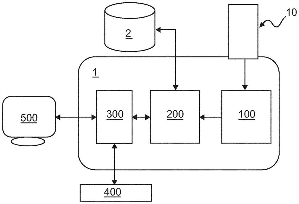
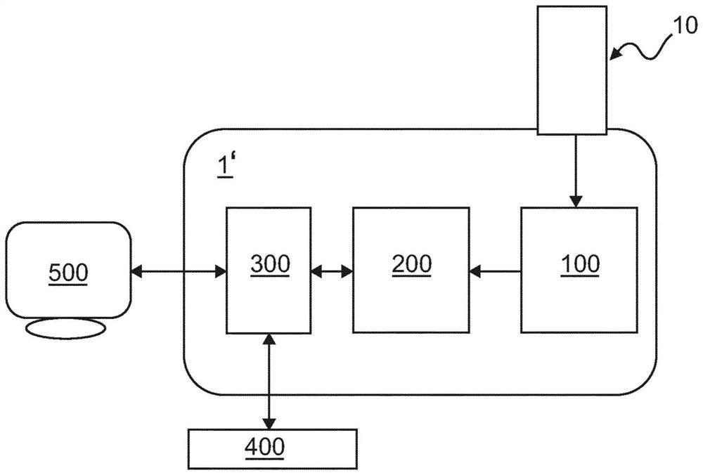
[0072] figure 1 A system 1 for medical treatment is illustrated according to an exemplary embodiment. The system 1 comprises an input unit 100, a processing unit 200, an analysis unit 300, a user interface 400 and a display unit 700, the input unit 100 is configured to receive the time series of the diagnostic map 10, the processing unit 200 is configured to process the time series of the diagnostic map 10 . Further, the system 1 is communicatively coupled to an external database 2 .

[0073] exist figure 1 In an exemplary embodiment of the invention, the treatment to be performed corresponds to a thermal ablation treatment. System 1 is thus used for treatment monitoring. The input unit 100 may receive a first time series of the diagnostic map 10 that has been measured in real time at a plurality of treatment time po...


PUM


Abstract

A system and a method for medical therapy, particularly ablation treatment, are provided in which diagnostic data may be processed and represented as a function of therapy time. This allows to appropriate plan and dynamically monitor thermal ablation therapy which significantly reduces the risks to damage organs and tissue outside the target area.

Description

technical field [0001] The invention relates to a system of medical treatments, a corresponding method and a corresponding computer program, in particular in the field of thermal ablation treatments. More specifically, the present invention relates to systems and methods for processing treatment data comprising histograms as a function of treatment time. Background technique [0002] Thermal therapy is a treatment modality that is increasingly used in cancer treatment in order to remove cancer growths. In this respect, thermal ablation techniques are generally regarded as a good alternative to common surgical techniques, since they are minimally invasive and thus allow to preserve as much surrounding biological tissue as possible. [0003] Similar to related radiation therapy techniques, the goal of thermal ablation therapy is to efficiently deliver thermal energy to a target area, such as a tumor, while keeping energy deposition in at-risk organs to a minimum. To achieve ...

Claims


Application Information

Patent Timeline
Patent Type & Authority Applications(China)
IPC IPC(8): A61N5/10G16H50/50A61B18/08A61B18/18A61N1/40A61B34/00
CPCG16H20/40G16H30/40G16H40/60G16H50/50A61B18/08A61B18/1815A61B34/10A61B2018/00577A61B2018/00886A61B2018/1869A61B2034/104A61N1/403A61N5/1027A61N5/103A61B34/25A61B18/04
Inventor J·L·库斯特拉G·L·T·F·豪特瓦斯特A·J·艾莱威尔特E·范戴克
Owner KONINKLJIJKE PHILIPS NV
Why Eureka
Try Eureka