Main body and electronic atomization device

An electronic atomization device and main body technology, applied in the field of tobacco, etc., can solve the problem of high identification cost of atomizers, and achieve the effect of reducing material and process costs

Inactive Publication Date: 2021-01-29
SHENZHEN SMOORE TECH LTD
View PDF5 Cites 0 Cited by
  • Summary
  • Abstract
  • Description
  • Claims
  • Application Information

AI Technical Summary

Problems solved by technology

[0004] The technical problem mainly solved by the present invention is to provide a main body and an electronic atomization device to solve the problem of high identification cost of the atomizer

Method used


Image

  • Main body and electronic atomization device
  • Main body and electronic atomization device
  • Main body and electronic atomization device

Examples


Embodiment 1

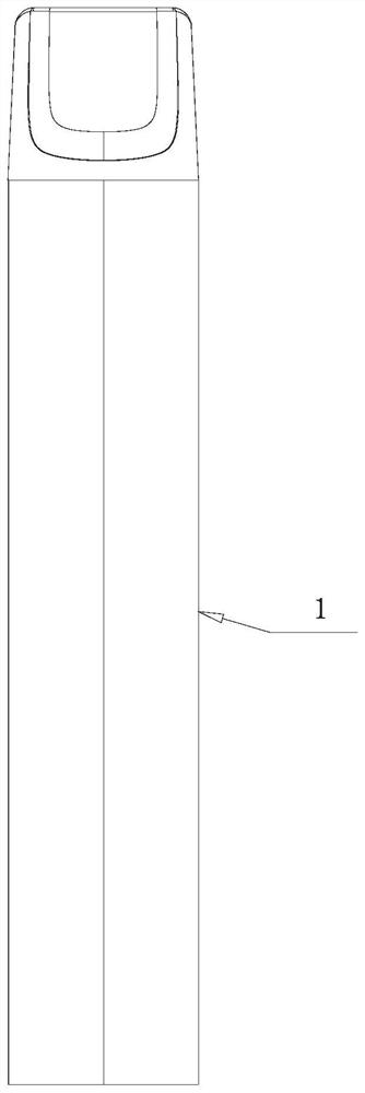
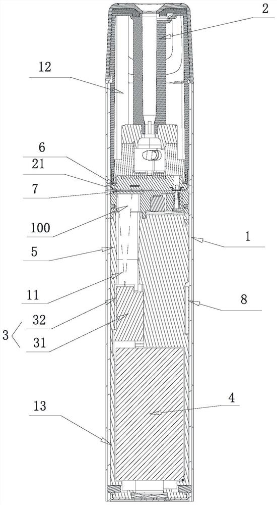
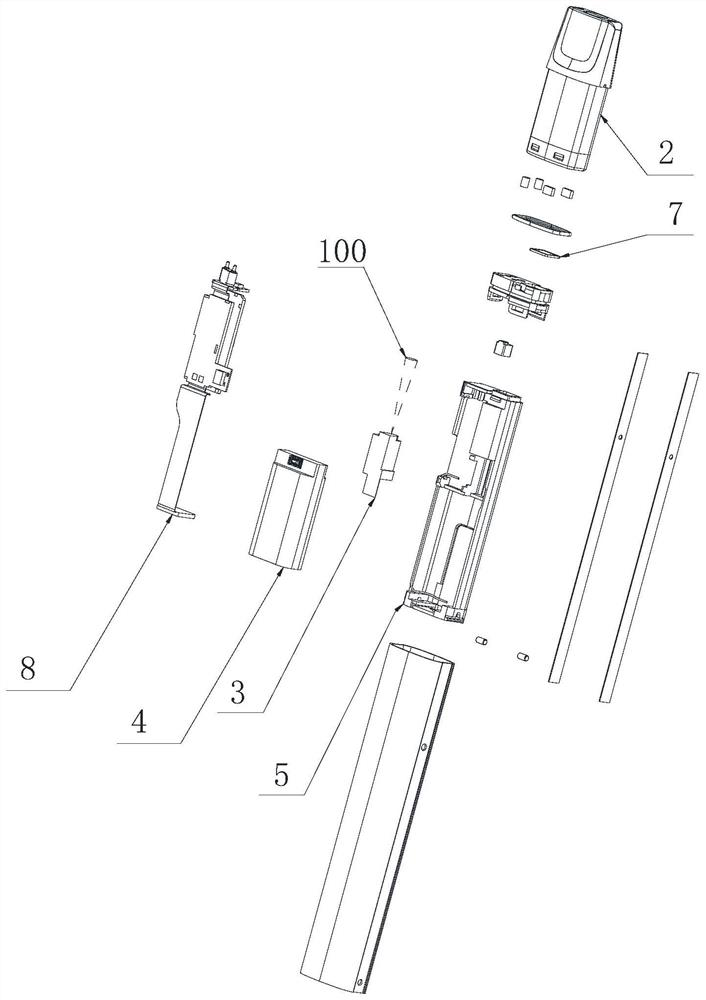
[0034] see Figure 1 to Figure 3 , figure 1 is a schematic diagram of the electronic atomization device of the present invention, figure 2 for figure 1 cutaway view of image 3 for figure 1 The disassembled structure schematic diagram of the electronic atomization device includes a detachable connection of the main body 1 and the atomizer 2 .

[0035] Wherein, the main body 1 is used for cooperating with the atomizer 2 provided with the identification pattern 21 .

[0036] The main body 1 is provided with a light sensor 3 and a control circuit 8, and the atomizer 2 is provided with an identification pattern 21, and the light sensor 3 is used to identify the identification pattern 21 when the main body 1 and the atomizer 2 are connected or matched to obtain The identification information, specifically, can be identified when the main body 1 and the atomizer 2 are electrically connected or mechanically connected to obtain the identification information; 1 When electricall...

Embodiment 2

[0091] see Figure 12-Figure 20 , the present invention also provides a main body 1, the main body 1 includes a light sensor 3 and a control circuit 8 electrically connected to each other. Specifically, the main body 1 can be used in cooperation with the atomizer 2 provided with a logo pattern 21 on the side. And the main body 1 can be detachably assembled with the atomizer 2, and the side of the atomizer 2 is provided with a logo pattern.

[0092] Wherein, the optical sensor 3 is used to identify the logo pattern 21 on the side of the atomizer 2 when the main body 1 is mated with the atomizer 2 to obtain logo information.

[0093]Optionally, the logo graphic 21 can be the label of the atomizer 2, or it can be a pattern, text, symbol, barcode or two-dimensional code or a dot matrix code arranged on the surface of the atomizer 2. The setting of the logo graphic 21 The method can be inkjet painting, laser engraving or printing. The above-mentioned labels, patterns, characters...

Embodiment 3

[0124] please see Figure 12-Figure 20 , the present application provides a main body 1, which is used to cooperate with an atomizer 2 provided with a logo pattern 21 . The main body 1 includes a light sensor 3 and a control circuit 8 electrically connected to each other.

[0125] Wherein, the optical sensor 3 is used to identify the logo pattern 21 on the side of the atomizer 2 when the main body 1 is mated with the atomizer 2 to obtain logo information. The control circuit 8 is used to control the atomizer 2 according to the identification information.

[0126] Wherein, the light sensor 3 further includes a lens 34 and a light-transmitting sheet 33 . The lens 34 can be used to capture the image of the logo graphic 21. Specifically, the lens 34 includes a collection direction. When the logo graphic 21 is located in the collection direction of the lens 34, the lens 34 can capture the image of the logo graphic 21. Wherein, the light-transmitting sheet 33 is also arranged in ...


PUM


Abstract

The invention discloses a main body and an electronic atomization device. The main body is used in cooperation with an atomizer provided with an identification pattern. The main body comprises an optical sensor and a control circuit which are electrically connected. The optical sensor is used for identifying the identification pattern of the atomizer to obtain identification information when the main body is matched with the atomizer. The control module is used for controlling the atomizer according to the identification information. The optical sensor comprises a lens used for collecting an image of the identification pattern and a light-transmitting piece located in the collecting direction of the lens, and when the main body is matched with the atomizer, the identification pattern of the atomizer is located on the side, away from the lens, of the light-transmitting piece and located in the collecting direction. By means of the mode, the atomizer can be recognized at low cost, and dust can be effectively prevented from entering the lens.

Description

technical field [0001] The invention relates to the technical field of electronic atomization, in particular to a main body and an electronic atomization device. Background technique [0002] The atomizer is generally detachably connected to the main body of the electronic atomization device, and the atomizer is a replaceable accessory. When the e-liquid in the atomizer is exhausted or the atomizer is damaged, the atomizer can be replaced. [0003] However, since the main body of the general electronic atomization device is paired with the atomizer, the control parameters of the paired atomizer are generally stored in the main body of the electronic atomization device, so as to achieve the best working effect of the atomizer. On the other hand, using a counterfeit atomizer may pose a safety hazard. In the existing technology, some electronic atomization products use the built-in identification chip of the atomizer to realize the function of identifying the atomizer, result...

Claims


Application Information

Patent Timeline
Patent Type & Authority Applications(China)
IPC IPC(8): A24F40/40A24F40/50A24F40/51A24F40/60
CPCA24F40/40A24F40/50A24F40/51A24F40/60
Inventor 谭华明志南沈丕发叶校威
Owner SHENZHEN SMOORE TECH LTD
Why Eureka
Try Eureka