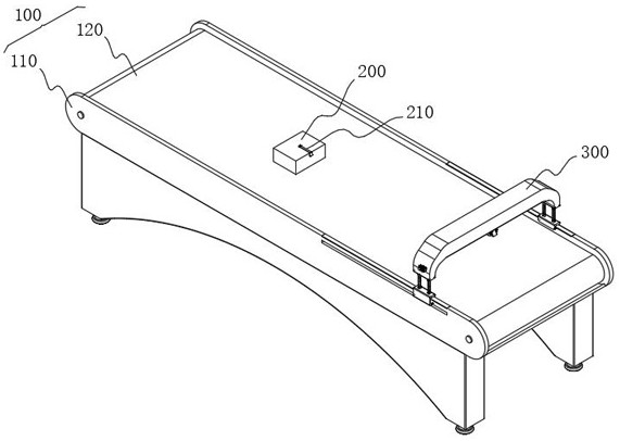
A conveying device for automatically recording data after goods leave the warehouse
A conveying device and automatic recording technology, which is applied in the direction of conveyor control devices, storage devices, conveyor objects, etc., can solve problems such as error-prone, low scanning accuracy, and difficult to scan goods labels, so as to improve accuracy and improve efficiency effect
- Summary
- Abstract
- Description
- Claims
- Application Information
AI Technical Summary
Problems solved by technology
Method used
Image
Examples
Embodiment 1
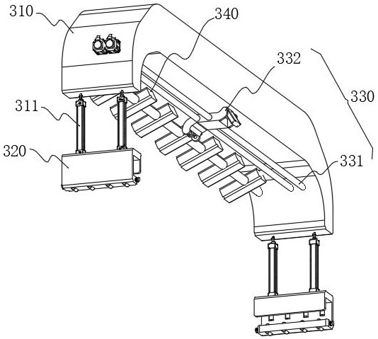
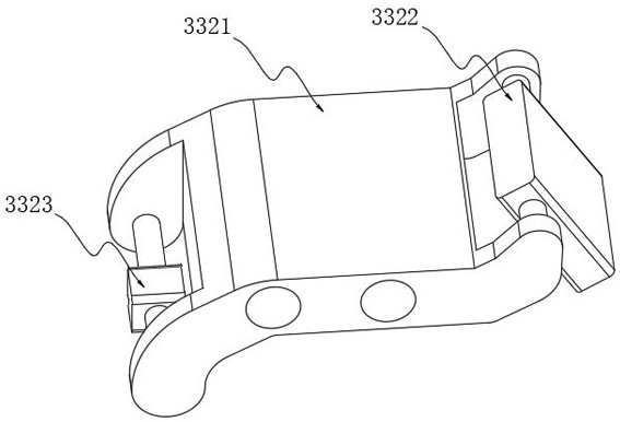
[0055] This embodiment specifically discloses the identification mechanism 300, please refer to figure 2 As shown, the front probe 340 is installed on one side of the bottom of the gantry 310, which is the direction in which the cargo body 200 is transported, and there are multiple front probes 340, and the multiple front probes 340 are arranged in the same row. The purpose is to carry out pre-identification (that is, early identification) to the cargo body 200 in transmission. The identification component 330 is arranged on the rear side of the front probe 340. The identification component 330 includes a screw 331 and an identification part 332. The screw 331 and the gantry Frame 310 is rotatably connected and driven by a motor. Identifying member 332 includes an integrated plate 3321, and the screw rod 331 is threadedly connected with the integrated plate 3321. When the screw rod 331 is driven by the motor at its end to rotate, the integrated plate is driven during the rotat...
Embodiment 2
[0059] see Figure 6 As shown, in order to adjust the recognized position, the moving plate 320 is slidingly connected with the bracket 110. Specifically, the top of the moving plate 320 is provided with a hook plate 321, and the hook plate 321 is connected with the moving plate 320 to form a “U” shape with an opening downward. structure, its main purpose is to position the mobile plate 320, the bottom of the mobile plate 320 is provided with a slide plate 322, and the slide plate 322 is connected with the mobile plate 320 to form an "L" shape structure, and its main purpose is to connect with the chute 111 on the side wall of the bracket 110 Sliding connection, so as to realize the sliding of the mobile plate 320 and the bracket 110, and the length of the chute 111 is opened according to the range that needs to be adjusted for the identification position. In addition:
[0060] In order to reduce the sliding frictional force of the movable plate 320, the inner walls of the mov...
Embodiment 3
[0064] This embodiment specifically discloses the front-end identification and recording system, please refer to Figure 8 and Figure 10 As shown, the system includes a pre-identification unit, a fixed-point identification unit and a storage unit, wherein:
[0065] The pre-identification unit includes a pre-label identification module, a delay calculation module and a delay information generation module. First, the pre-label identification module identifies the pre-label on the pre-region surface 213 through the pre-probe 340. Contain the distance of the connecting band 212 in the tag, and send the identified distance to the delay calculation module, and the delay calculation module calculates, and its calculation formula is as follows:
[0066] T=(l+L) / V;
[0067] see Figure 9 As shown, wherein, T is the time that the identification probe 3323 needs to be delayed; l is the distance from the connection belt 212 obtained by identifying the front label; L is the recognition...
PUM
 Abstract
Description
Claims
Application Information
 - R&D
- Intellectual Property
- Life Sciences
- Materials
- Tech Scout
- Unparalleled Data Quality
- Higher Quality Content
- 60% Fewer Hallucinations
Browse by: Latest US Patents, China's latest patents, Technical Efficacy Thesaurus, Application Domain, Technology Topic, Popular Technical Reports.
© 2025 PatSnap. All rights reserved.Legal|Privacy policy|Modern Slavery Act Transparency Statement|Sitemap|About US| Contact US: help@patsnap.com


