Special bed for gynecological examination

A technology for gynecological examinations and special beds, which is applied in medical science, lighting devices, components of lighting devices, etc., can solve problems such as lighting and low efficiency, and achieve the effects of improving work efficiency, improving efficiency and saving manpower.

Pending Publication Date: 2021-01-29
耿媚
View PDF23 Cites 2 Cited by
  • Summary
  • Abstract
  • Description
  • Claims
  • Application Information

AI Technical Summary

Problems solved by technology

[0005] In order to overcome the disadvantages of the above-mentioned patents that it cannot be illuminated during gynecological examinations and the efficiency is low, the technical problem to be solved by the present invention is to provide a special bed for gynecological examinations that can be illuminated during examinations

Method used


Image

  • Special bed for gynecological examination
  • Special bed for gynecological examination
  • Special bed for gynecological examination

Examples


Embodiment 1

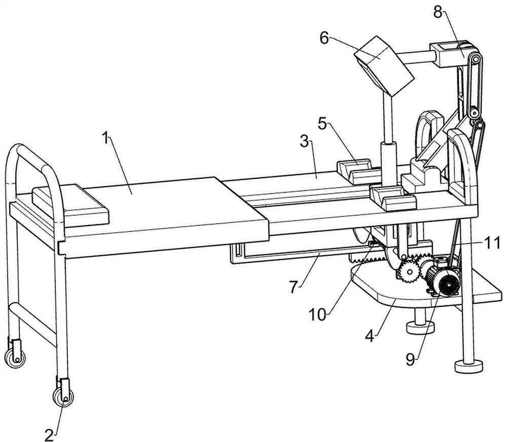
[0027] A special bed for gynecological examination, such as figure 1 and figure 2 As shown, it includes left half bed 1, wheels 2, right half bed 3, placing board 4, lifting assembly 5 and lighting assembly 6. The bottom of the left half bed 1 is provided with a wheel 2, and the right side of the left half bed 1 is slidably connected with a The right half bed 3 is connected with a placing board 4 on the lower part of the right side of the right half bed 3, a lifting assembly 5 is connected on the right side of the right half bed 3, and a lighting assembly 6 is slidably connected on the right side of the right half bed 3.

[0028] The lifting assembly 5 includes a support block 51, a first rotating shaft 52 and a cam 53, two support blocks 51 are slidably connected to the right side of the right half bed 3, and a first rotating shaft 52 is rotatably connected to the bottom right side of the right half bed 3. A cam 53 is connected to the front and rear sides of a rotating shaf...

Embodiment 2

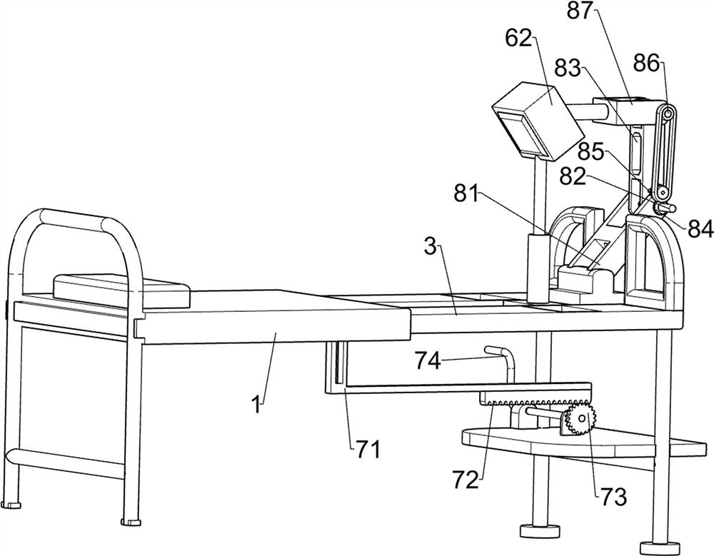
[0032] On the basis of Example 1, as image 3 As shown, it also includes a left and right assembly 7, the left and right assembly 7 includes an L-shaped rod 71, a long rack 72, a first gear 73 and a handle 74, and the bottom of the left half bed 1 is connected with an L-shaped rod 71, and the L-shaped rod A long rack 72 is connected to the bottom of the right side of 71 , a first gear 73 is rotatably connected to the top of the placing plate 4 , the first gear 73 is engaged with the long rack 72 , and a handle 74 is connected to the rear of the long rack 72 .

[0033] When the patient is lying on the left half bed 1, manually turning the handle 74 drives the first gear 73 to rotate, the first gear 73 rotates to drive the long rack 72 to move to the right, and the long rack 72 moves to the right to drive the left half bed 1 to the right Therefore, there is no need to manually push the left half bed 1 to move to the right, saving manpower and improving work efficiency.

Embodiment 3

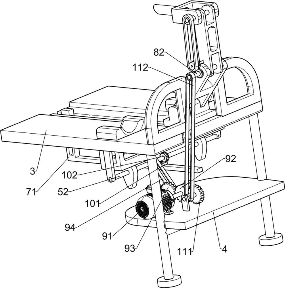
[0035] On the basis of Example 2, as image 3 and Figure 4 As shown, an auxiliary assembly 8 is also included. The auxiliary assembly 8 includes a support plate 81 , a second rotating shaft 82 , a first connecting rod 83 , a second gear 84 , a third gear 85 , a third rotating shaft 86 and a second connecting rod 87 . , a support plate 81 is connected to the top of the right side of the right half bed 3, the top of the support plate 81 is rotatably connected to a second shaft 82, the second shaft 82 is connected to a first connecting rod 83, and the front side of the second shaft 82 is connected to a second Gear 84, the lower part of the front side of the first connecting rod 83 is rotatably connected with a third gear 85, the third gear 85 is meshed with the second gear 84, the top of the first connecting rod 83 is rotatably connected with a third rotating shaft 86, the third rotating shaft A second connecting rod 87 is connected to the 86 , and the left end of the second co...


PUM


Abstract

The invention relates to a bed, in particular to a bed special for gynecological examination. The invention aims to provide a special bed for gynecological examination, which can be used for illumination assistance during examination. In order to solve the technical problem, the special bed for gynecological examination comprises a left half bed, wherein wheels are arranged on the bottom of the left half bed; a right half bed, which is connected to the left half bed in a sliding manner; a placing plate, which is connected to the right half bed; a lifting assembly, which is connected to the right half bed; and a lighting assembly, which is connected to the right half bed in a sliding manner. The special bed has the advantages that through a lifting assembly and a lighting assembly, the legsof a patient can be lifted and lighted during examination.

Description

technical field [0001] The invention relates to a bed, in particular to a special bed for gynecological examination. Background technique [0002] With the rapid development of society, the continuous improvement of medical level, and the continuous improvement of medical equipment, people will choose to go to the hospital for health check when they are not feeling well. When performing gynecological examinations, doctors need to visually observe them, so it is necessary to design A special examination bed that can assist lighting and is suitable for different heights. [0003] After retrieval, the patent publication number is: CN204636776U, which discloses a hospital bed for maintaining lower limbs raised, including a bed frame, a bed board and a support. The bed board is laid on the bed frame. The rear plate is formed by hinged in turn. The further design of the hospital bed for maintaining lower limbs is that the support is a self-locking gas spring with a valve core in ...

Claims


Application Information

Patent Timeline
Patent Type & Authority Applications(China)
IPC IPC(8): A61G13/02A61G13/10A61G13/12F21V33/00
CPCA61G13/02A61G13/10A61G13/1245F21V33/0072
Inventor 耿媚
Owner 耿媚
Why Eureka
Try Eureka