Chemical waste gas extraction equipment with long service life
A long-life, chemical technology, used in the use of liquid separation agents, chemical instruments and methods, and dispersed particle separation, etc., can solve problems such as easy damage, affecting the normal service life of equipment, and accelerating the aging of electronic components in the equipment, and achieves high Efficiency, the effect of accelerated cooling treatment
- Summary
- Abstract
- Description
- Claims
- Application Information
AI Technical Summary
Problems solved by technology
Method used
Image
Examples
Embodiment 1
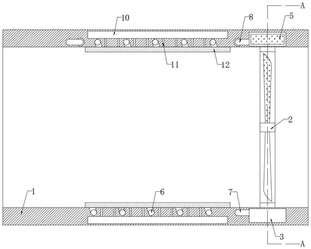
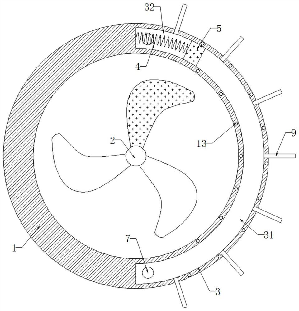
[0021] refer to Figure 1-2 , a chemical waste gas extraction device with a long service life, including a housing 1, the inner wall of the housing 1 is fixedly connected with a fan 2, one of the fan blades on the fan 2 is made of magnetic material, and the housing 1 is provided with an arc-shaped cavity 3 , the arc-shaped cavity 3 is provided with cooling liquid, and the inner wall of the arc-shaped cavity 3 is fixedly connected with a plurality of cooling fins 9, which is convenient for dissipating the heat in the cooling liquid, so that the cooling liquid always maintains a lower temperature, and the inner wall of the arc-shaped cavity 3 There is a magnetic sliding plug 5 in the sealing and sliding connection. The magnetic sliding plug 5 divides the inner wall of the arc chamber 3 into a liquid outlet chamber 31 and a liquid suction chamber 32. The side wall of the magnetic sliding plug 5 is elastically connected with the inner wall of the arc chamber 3 through a spring 4. ...
Embodiment 2
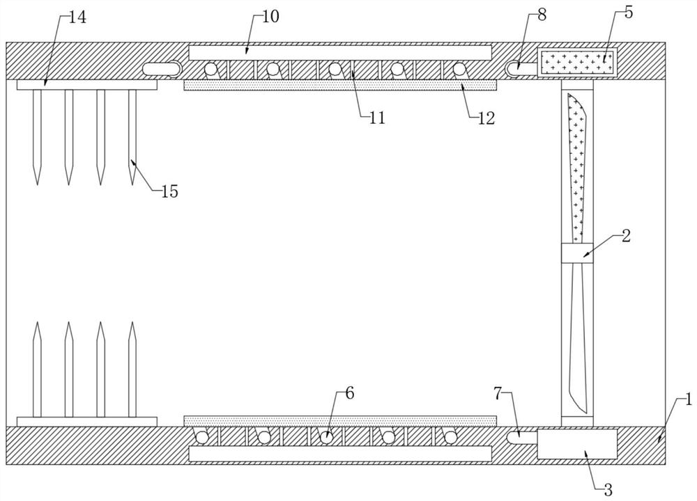
[0025] refer to image 3 , and the difference from Embodiment 1 is that the inner wall of the housing 1 is symmetrically fixedly connected with two collector plates 14, and the opposite side walls of the two collector plates 14 are evenly distributed and fixedly connected with a plurality of discharge needles 15, and are located between the two collector plates. The discharge needles 15 on the side walls of the plates 14 are matched one by one and the tips are facing and not in contact. One collector plate 14 is coupled to the positive pole of the helical coil 13 , and the other collector plate 14 is coupled to the negative pole of the helical coil 13 .
[0026] In this embodiment, when the induction current is generated on the spiral coil 13, a large amount of positive and negative charges respectively accumulated on the two discharge needles 15 through the collector plate 14, under the action of the tip effect, when the two discharge needles 15 are on the When the inductive ...
PUM
 Abstract
Description
Claims
Application Information
 - R&D
- Intellectual Property
- Life Sciences
- Materials
- Tech Scout
- Unparalleled Data Quality
- Higher Quality Content
- 60% Fewer Hallucinations
Browse by: Latest US Patents, China's latest patents, Technical Efficacy Thesaurus, Application Domain, Technology Topic, Popular Technical Reports.
© 2025 PatSnap. All rights reserved.Legal|Privacy policy|Modern Slavery Act Transparency Statement|Sitemap|About US| Contact US: help@patsnap.com


