Water-bath constant-temperature oscillator for laboratory

A technology of constant temperature oscillator and water bath, which is applied in laboratory equipment, water bath/sand bath/air bath, specific-purpose bioreactor/fermenter, etc., can solve the problems of high cost and low service life, and achieve improvement Longer service life, lower heat loss, and lower cost effects

Inactive Publication Date: 2021-01-29
王超艳
View PDF0 Cites 1 Cited by
  • Summary
  • Abstract
  • Description
  • Claims
  • Application Information

AI Technical Summary

Problems solved by technology

[0005] The purpose of the present invention is to provide a long service life and low cost laboratory water bath constant temperature oscillator for the above-mentioned problems of low service life and high cost

Method used


Image

  • Water-bath constant-temperature oscillator for laboratory
  • Water-bath constant-temperature oscillator for laboratory

Examples


Embodiment 1

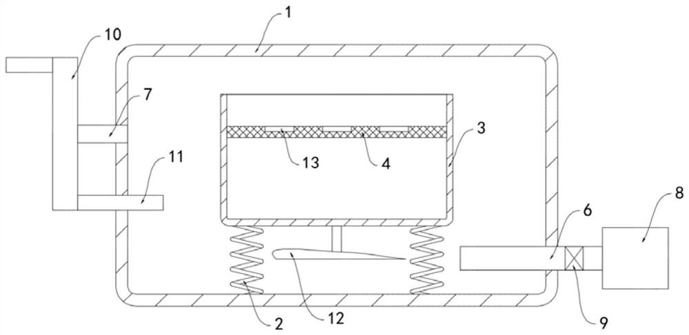
[0019] Such as figure 1 As shown, a laboratory water bath constant temperature oscillator includes a housing 1, the inner bottom surface of the housing 1 is fixedly connected with a water bath box 3 through a support spring 2, and a horizontal placing mesh plate 4 is provided in the water bath box 3, and a placing mesh The upper surface of the plate 4 is equipped with a plurality of fixed grooves 13 in an equidistant array. The fixed grooves 13 are convenient for the orderly and stable placement of the culture container, and are conducive to the rapid progress of the experiment. Trachea 6 and exhaust pipe 7, blower fan 8 is installed on the inlet end of air inlet pipe 6, is provided with solenoid valve 9 in the air inlet pipe 6, and the exhaust end of exhaust pipe 7 is fixedly communicated with vortex tube 10, and the heat of vortex tube 10 One end is fixedly connected with a return pipe 11, and the other end of the return pipe 11 runs through the side wall of the housing 1 an...

Embodiment 2

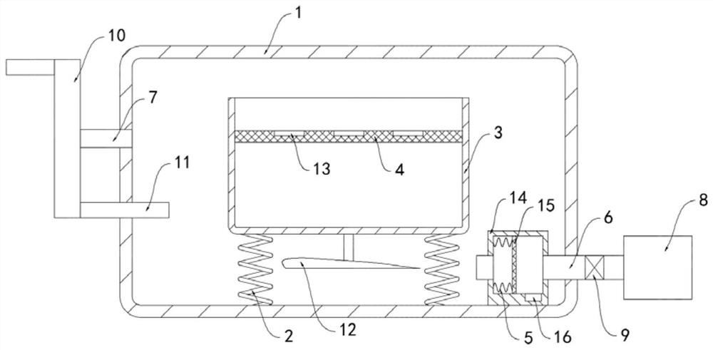
[0023] Such as figure 2 As shown, the difference between this embodiment and Embodiment 1 is that a dust removal box 14 is fixedly installed on the inner bottom surface of the housing 1, the dust removal box 14 communicates with the air intake pipe 6, and there is a vertically arranged filter in the inner slide of the dust removal box 14. Screen plate 15, filter screen plate 15 is fixedly connected with the inner side wall of dust removal box 14 by vibrating spring 5, and the inner bottom surface of dust removal box 14 is provided with dust collection groove 16.

[0024] In this embodiment, the filter screen plate 15 can filter out the dust carried in the intake air flow, and under the blowing of the air flow, the filter screen plate 15 can push the vibrating spring 5 to compress, and then the electromagnetic valve 9 opens and closes intermittently, vibrating The spring 5 drives the filter plate 15 to vibrate back and forth, and the dust covered on the surface of the filter p...


PUM


Abstract

The invention belongs to the field of oscillators for experiments, and particularly relates to a water-bath constant-temperature oscillator for a laboratory. The oscillator comprises a shell, whereinthe inner bottom surface of the shell is fixedly connected with a water bath box through a supporting spring, a horizontal placement screen plate is arranged in the water bath box, the side walls of the two sides of the shell are respectively and fixedly communicated with an air inlet pipe and an air outlet pipe, a draught fan is installed at the air inlet end of the air inlet pipe, an electromagnetic valve is arranged in the air inlet pipe, the air outlet end of the air outlet pipe is fixedly communicated with a vortex pipe, the hot end of the vortex pipe is fixedly communicated with a backflow pipe, the other end of the backflow pipe penetrates through the side wall of the shell and extends into the water bath box, the lower surface of the water bath box is fixedly connected with a wingplate through a supporting rod, and the wing plate is horizontally arranged. The electromagnetic valve can be controlled to be opened and closed intermittently to drive the wing plate to vibrate up and down in a reciprocating mode, no friction is generated in the vibration process, the friction loss is reduced, the service life is prolonged, and the influence of generated noise on the laboratory environment is avoided.

Description

technical field [0001] The invention belongs to the field of experimental oscillators, in particular to a laboratory water bath constant temperature oscillator. Background technique [0002] The constant temperature water bath shaker is a biochemical instrument that combines a temperature controllable constant temperature water bath and a shaker. It can vibrate and shake the container. It is often used in the culture of microorganisms and cells in the laboratory. [0003] Most of the traditional water bath constant temperature oscillators use mechanical vibration to oscillate and shake well. This method is prone to wear and noise during work, has a short service life, and produces noise pollution. It is not convenient for use in the laboratory, and the water bath constant temperature In order to ensure uniform temperature throughout the box, the oscillator needs forced ventilation. However, the air flow easily carries the temperature inside the box and discharges it, resulti...

Claims


Application Information

Patent Timeline
Patent Type & Authority Applications(China)
IPC IPC(8): B01L7/02B01L9/00B01D46/00B01D46/10C12M3/00C12M1/08
CPCB01L7/02B01L9/00C12M29/06C12M41/22B01D46/10B01D46/76
Inventor 王超艳
Owner 王超艳
Why Eureka
Try Eureka