Supercharge Your Innovation With Domain-Expert AI Agents!

Limiting floating offshore new energy charging pile

A charging pile and new energy technology, applied in charging stations, electric vehicle charging technology, electric vehicles, etc., can solve the problems of unstable power output, low power output, and high construction investment, and achieve time saving, stable placement process and quick effect

Inactive Publication Date: 2021-01-29
台州任雪电子科技有限公司
View PDF0 Cites 0 Cited by
  • Summary
  • Abstract
  • Description
  • Claims
  • Application Information

AI Technical Summary

Problems solved by technology

[0002] New energy charging piles can develop and utilize a large amount of energy contained in the ocean. On the one hand, it can effectively improve the utilization rate of clean energy, and on the other hand, it can also effectively support the construction of islands and the improvement of coastal defense capabilities. How to efficiently develop and utilize renewable resources is the direction that researchers have been working on. As an independent device installed on the sea, offshore charging piles can use renewable energy in the ocean to generate electricity and output energy for various electrical equipment at sea. , but based on the diversity and complexity of the marine environment, single-energy power generation equipment and general offshore energy island devices have the problems of unstable power output, high construction investment, and low power output

Method used


Image

  • Limiting floating offshore new energy charging pile
  • Limiting floating offshore new energy charging pile

Examples


Embodiment Construction

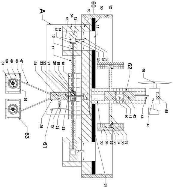
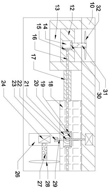
[0013] Combine below Figure 1-2 The present invention is described in detail, wherein, for the convenience of description, the orientations mentioned below are defined as follows: figure 1 The up, down, left, right, front and back directions of the projection relationship itself are the same.

[0014] combined with Figure 1-2 The above-mentioned offshore new energy charging pile with limited floating includes a floating board 10, the floating board 10 includes a charging device 60, and the charging device 60 includes a wireless charging pile fixed on the upper end surface of the floating board 10. Charging plate 53, the wireless charging plate 53 is used to charge the drone, and the side of the floating plate 10 is provided with a magnetic suction wireless charging ring 52, and the magnetic suction wireless charging ring 52 is used for magnetically attracting electric ships on the sea. It performs wireless charging;

[0015] Four annular tubes 54 are arranged in the annul...


PUM


Abstract

The invention discloses a limiting floating offshore new energy charging pile. The charging pile comprises a floating plate, wherein the floating plate comprises a charging device, the charging devicecomprises a wireless charging plate fixedly arranged on the upper end face of the floating plate, the wireless charging plate is used for charging an unmanned aerial vehicle, and a magnetic attraction wireless charging ring is arranged on the side face of the floating plate; the magnetic attraction wireless charging ring is used for magnetically attracting an offshore electric ship and wirelesslycharging the offshore electric ship, four annular cylinders are arranged on the lower end face of the floating plate in an annular array mode, and buoyancy cavities penetrating through the upper endfaces and the lower end faces of the annular cylinders are formed in the annular cylinders; the duration of the ship at sea is increased, the marine charging pile can be rapidly moved to the positionnear the ship on the sea surface through the moving mechanism, meanwhile, the charging process is stable and rapid, the marine charging pile is pulled back through the limiting mechanism after charging is completed, and the marine charging pile is prevented from floating in the sea.

Description

technical field [0001] The invention relates to the related field of new energy charging piles, in particular to a limited floating offshore new energy charging pile. Background technique [0002] New energy charging piles can develop and utilize a large amount of energy contained in the ocean. On the one hand, it can effectively improve the utilization rate of clean energy, and on the other hand, it can also effectively support the construction of islands and the improvement of coastal defense capabilities. How to efficiently develop and utilize renewable resources is the direction that researchers have been working on. As an independent device installed on the sea, offshore charging piles can use renewable energy in the ocean to generate electricity and output energy for various electrical equipment at sea. , but based on the diversity and complexity of the marine environment, single-energy power generation equipment and general offshore energy island devices have the prob...

Claims


Application Information

Patent Timeline
IPC IPC(8): B60L53/31B60L53/12B60L53/51B60L53/52B63H1/14
CPCB60L2200/10B60L2200/32B63H1/14B60L53/12B60L53/31B60L53/51B60L53/52Y02T10/70Y02T10/7072Y02T90/12Y02T90/14
Inventor 贾乐拉
Owner 台州任雪电子科技有限公司
Features
  • R&D
  • Intellectual Property
  • Life Sciences
  • Materials
  • Tech Scout
  • Unparalleled Data Quality
  • Higher Quality Content
  • 60% Fewer Hallucinations
Learn More