Lifting mechanism of bridge crane

A technology for bridge cranes and driving motors, which is applied in the direction of clockwork mechanism, engine lubrication, mechanical equipment, etc. It can solve the problems of reduced service life of steel wire ropes, increase lifting gravity, and damage to steel wire ropes, so as to reduce friction damage and reduce Friction, the effect of lifting objects easily

Inactive Publication Date: 2021-01-29
信华智能装备(江苏)有限公司
View PDF5 Cites 2 Cited by
  • Summary
  • Abstract
  • Description
  • Claims
  • Application Information

AI Technical Summary

Problems solved by technology

[0005] The purpose of the present invention is to provide a hoisting mechanism of a bridge crane to solve the problem that the existing hoisting mechanism proposed in the background art mentioned above will cause problems between the steel wires or between the steel wire rope and the reel when the steel wire rope is shrunk when hoisting heavy objects. At the same time, the steel wire rope moves on the surface of the pulley and a certain friction force is generated between the pulley. Under the action of the friction force, it will not only increase the lifting gravity of the lifting, but also damage the steel wire rope, resulting in a greatly reduced service life of the steel wire rope. , resulting in a waste of resources

Method used


Image

  • Lifting mechanism of bridge crane
  • Lifting mechanism of bridge crane
  • Lifting mechanism of bridge crane

Examples


Embodiment Construction

[0024] The following will clearly and completely describe the technical solutions in the embodiments of the present invention with reference to the accompanying drawings in the embodiments of the present invention. Obviously, the described embodiments are only some, not all, embodiments of the present invention. Based on the embodiments of the present invention, all other embodiments obtained by persons of ordinary skill in the art without making creative efforts belong to the protection scope of the present invention.

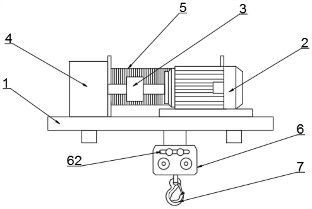
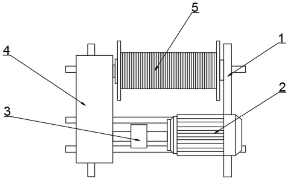
[0025] see Figure 1-6 , the present invention provides a technical solution: a lifting mechanism of a bridge crane, including a base 1, a drive motor 2, a reel 5 and a pulley assembly 6, the drive motor 2 is connected to the upper end of one side of the base 1 by bolts, and the other side The upper end of the bolt is connected with a reducer 4, one end of the reducer 4 is connected to the reel 5 in transmission, the surface of the reel 5 is wound with a steel...


PUM


Abstract

The invention discloses a lifting mechanism of a bridge crane. The lifting mechanism comprises a base, a driving motor, a winding drum and a pulley assembly, wherein the upper end of one side of the base is in bolted connection with the driving motor; the upper end of the other side of the base is in bolted connection with a speed reducer; one end of the speed reducer is in transmission connectionwith the winding drum; a steel wire is wound on the surface of the winding drum; the pulley assembly is arranged at the end, away from the winding drum, of the surface of the steel wire; and a lifting hook is fixedly installed at the bottom end of the pulley assembly. According to the lifting mechanism, a bearing is arranged between a rotating wheel and a plug pin, the rotating wheel is rotationally connected with the plug pin through the bearing, when a steel wire rope contracts, the friction force between the rotating wheel and the plug pin is reduced, so that the steel wire rope can betterdrive the rotating wheel, and the friction force between the steel wire rope and the rotating wheel is reduced; and meanwhile, rolling wheels are arranged on the two sides of the interior of a shell,so that the friction force between a side plate and the inner wall of the shell is reduced in the moving process of the steel wire rope, the lifting mechanism can lift objects more easily, and then the friction damage of the steel wire rope is reduced.

Description

technical field [0001] The invention relates to the technical field of cranes, in particular to a lifting mechanism of a bridge crane. Background technique [0002] A crane refers to a multi-action hoisting machine that lifts vertically and carries heavy objects horizontally within a certain range. Also known as crane, aerial crane, crane. The bridge crane is a lifting device that is horizontally placed over the workshop, warehouse and stockyard for material lifting. Because its two ends are located on tall concrete pillars or metal supports, it is shaped like a bridge. The bridge frame of the bridge crane runs longitudinally along the tracks laid on the elevated sides on both sides, which can make full use of the space under the bridge frame to lift materials without being hindered by ground equipment. It is a kind of hoisting machinery with the widest range and the largest number. [0003] The hoisting mechanism, also called "hoisting mechanism", is the basic structure...

Claims


Application Information

Patent Timeline
Patent Type & Authority Applications(China)
IPC IPC(8): B66C11/02B66C11/16B66D1/12B66D1/28B66D1/36F16N11/00
CPCB66C11/02B66C11/16B66D1/12B66D1/28B66D1/36F16N11/00
Inventor 高超
Owner 信华智能装备(江苏)有限公司
Why Eureka
Try Eureka