
Multi-stage self-transmission swing arm lifting device

A lifting device, self-transmission pendulum technology, applied in the direction of lifting device, lifting frame, etc., can solve the problems of easy inclination, unfavorable placement, large space on the bottom of the lifting device, etc., to achieve powerful functions, simplified structure, and solve the change of lifting height. Effect

Pending Publication Date: 2021-01-29
SHANGHAI YUKE MACHINERY CO LTD
View PDF0 Cites 0 Cited by
  • Summary
  • Abstract
  • Description
  • Claims
  • Application Information

AI Technical Summary

Problems solved by technology

However, most of the existing lifting devices rely on the bottom surface for installation, and the lifting device occupies a large space on the bottom surface, which is not conducive to placement; and the multi-layer lifting device is not stable enough, and it is prone to tilt problems

Method used


Image

  • Multi-stage self-transmission swing arm lifting device
  • Multi-stage self-transmission swing arm lifting device
  • Multi-stage self-transmission swing arm lifting device

Examples


Embodiment

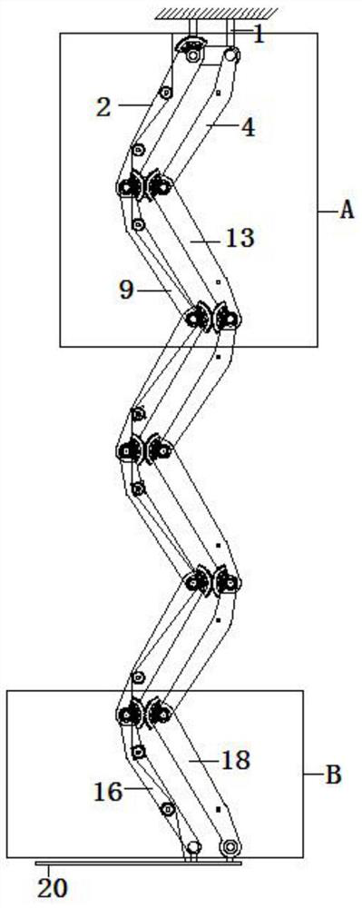
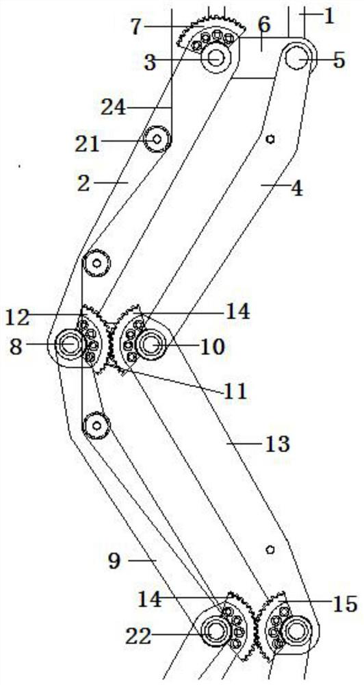
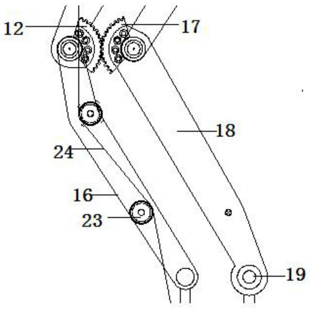
[0016] Such as Figure 1-Figure 4 The shown multi-stage self-driving swing arm lifting device includes an upper fixing part 1, the upper shaft 3 of the primary transmission arm 2 and the upper shaft I5 of the primary link arm 4 are connected below the upper fixing part 1, and the upper shaft 3 It is connected with the upper shaft I5 through the coupling shaft seat 6, the upper shaft 3 is equipped with a 0-stage transmission gear 7, the bottom of the primary transmission arm 2 is installed on the lower shaft 8, and is coaxially connected with the grading link arm 9, and the primary The bottom of the connecting rod arm 4 is installed on the lower shaft I10, the lower shaft 8 and the lower shaft I10 are connected through the coupling seat I11, the primary transmission gear 12 is installed on the lower shaft 8, and the primary transmission gear 12 is connected to the top of the stepping transmission arm 13 The upper gear 14 meshes, the upper gear 14 is coaxially connected with the...


PUM


Abstract

The invention discloses a multi-stage self-transmission swing arm lifting device which comprises an upper fixing piece. The lower portion of the upper fixing piece is connected with a first-stage transmission mechanism, the bottom of the first-stage transmission mechanism is connected with a staged transmission mechanism, the bottom of the staged transmission mechanism is connected with a final-stage transmission mechanism, and the final-stage transmission mechanism is connected with a lifting platform. Each stage of transmission of the device adopts double-linking-plate synchronization, the rotating shaft distance, the mounting distance and the like are constant, and synchronization and stability are kept. Each stage of linking plates are in cross transmission, and transmission units anda lifting structure are highly integrated, so that the structure is simplified, and functions are powerful.

Description

technical field [0001] The invention relates to the technical field of lifting devices, in particular to a multi-stage self-driving swing arm lifting device. Background technique [0002] The lifting device is a common tool in the building materials industry, such as the timber industry, etc. It can help employees transport timber and other items to different heights for installation; or transport timber to different heights for stacking to save space. The use of lifting devices in the timber industry improves the work efficiency of workers and also improves the operating safety of employees. However, most of the existing lifting devices rely on the bottom surface for installation, and the lifting device occupies a large space on the bottom surface, which is not conducive to placement; and the multi-layer lifting device is not stable enough, and it is prone to the problem of inclination. Contents of the invention [0003] The object of the present invention is to provide ...

Claims


Application Information

Patent Timeline
IPC IPC(8): B66F7/06B66F7/28
CPCB66F7/0616B66F7/0641B66F7/28
Inventor 喻玉芹
Owner SHANGHAI YUKE MACHINERY CO LTD
Learn More