Step ladder-shaped pedestrian ladder and loading ramp conversion device and using method

A conversion device and step ladder technology, which is applied in the direction of ramps, stairs, building structures, etc., can solve the problems of repeated installation and dismantling, inability to change the position, and large footprint, and achieve compact structure, low cost, and applicability strong effect

Active Publication Date: 2022-03-01
NORTHEASTERN UNIV LIAONING
View PDF6 Cites 0 Cited by
  • Summary
  • Abstract
  • Description
  • Claims
  • Application Information

AI Technical Summary

Problems solved by technology

This device solves the limitations of the current step ladder slides such as fixed, bulky, large footprint, unable to change the position, unable to be repeatedly installed and dismantled, etc.

Method used


Image

  • Step ladder-shaped pedestrian ladder and loading ramp conversion device and using method
  • Step ladder-shaped pedestrian ladder and loading ramp conversion device and using method
  • Step ladder-shaped pedestrian ladder and loading ramp conversion device and using method

Examples


Embodiment 1

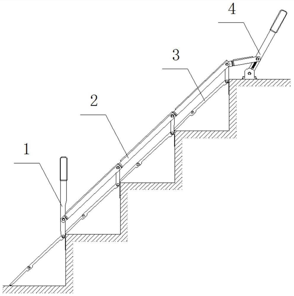
[0060] like Figure 1 to Figure 15 As shown, the ladder-shaped pedestrian ladder and loading ramp conversion device includes an upper pull rod 4, a lower rod 1, a connecting rod 2 and a folding step surface 3, and the upper pull rod 4 and the lower rod 1 are respectively installed on the top of the walking ladder. On the horizontal plane of the step and on the vertical plane of the bottommost step, the upper tie rod 4 is connected to the lower rod 1 through a plurality of connecting rods 2, and between the upper tie rod 4 and the connecting rods 2 and between two adjacent connecting rods 2 Both are provided with rotating rods 11 , and folding step surfaces 3 are provided between adjacent rotating rods 11 , between rotating rods 11 and the pull-down rod 1 , and between the pull-down rod 1 and the ground.

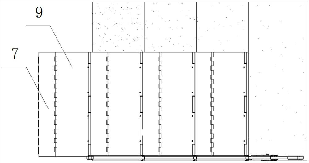
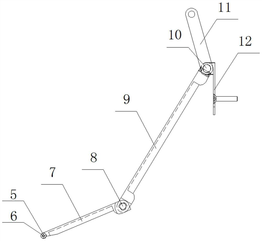
[0061] The folding step surface 3 includes a lower step surface 7 and an upper step surface 9. A cylindrical roller 5 is installed at the front of the lower step surface 7, a...

Embodiment 2

[0067] like Figure 16 to Figure 31 As shown, the ladder-shaped pedestrian ladder and load ramp conversion device includes an upper pull rod 4, a lower rod 1, a connecting rod 2, a comb-toothed step surface 18 and a driving rod 17; the comb-toothed stepped surface 18 passes through the main body mounting plate 19 and the expansion bolt passing through the main body mounting plate 19 are fixed on the vertical surface of the step ladder step, the bottom end of the upper pull rod 4 is connected with the bottom end of the main body mounting plate 19 at the topmost place through a pin shaft, and the lower rod 1 The bottom end is connected to the bottom end of the main body mounting plate 19 located at the bottom end through a pin shaft, and the upper pull rod 4 and the lower rod 1 are connected through a plurality of connecting rods 2, and the pin shaft ends between the two connecting rods 2 The part is connected with driving lever 17 one end, and driving lever 17 other end is conn...


PUM


Abstract

The ladder-shaped pedestrian ladder and loading ramp conversion device and its use method are divided into two forms. The first form is composed of upper pull rod, lower rod, connecting rod and folding step surface. The second form is composed of upper pull rod, lower It is composed of tie rods, connecting rods, comb-toothed steps and connecting rods; the device is portable for installation and disassembly, and does not damage the structure of the steps to the greatest extent. Drill installation holes on the vertical surface of the step ladder and fix it with expansion bolts to complete the installation work of the whole device. The structure is compact and has little impact on the function of the original step ladder. Strong applicability, adapt to the requirements of steps of different heights by replacing parts. The invention has a purely mechanical structure and can still be used normally when the power is cut off. It has a wide range of applications and can work in an environment without electricity, such as old residential buildings; and the device has a simple structure, easy maintenance, and low cost.

Description

technical field [0001] The invention belongs to the technical field of mechanical loading ramps, and in particular relates to a conversion device and a use method of a ladder-shaped pedestrian step ladder and a loading ramp. Background technique [0002] Step ladders are widely used in buildings, such as railway stations, subway stations, high-speed rail stations, docks, squares, overpasses and other places. With the progress of the times, fixed steps have also exposed some problems: the implementation of bicycles or electric vehicles The current common solution is: one is to directly put cement on the steps to make a permanent slope slide, but it will affect the beauty of the original steps, and the narrow steps are not suitable The 2nd, increase the slope slideway device on one side or both sides of the step ladder, but ubiquitous structure is too complicated, bigger to the step ladder structure change and damage the shortcomings such as step ladder body. [0003] The mai...

Claims


Application Information

Patent Timeline
Patent Type & Authority Patents(China)
IPC IPC(8): E04F11/00E04F11/02
CPCE04F11/002E04F11/00E04F11/02E04F2011/005
Inventor 杨松
Owner NORTHEASTERN UNIV LIAONING
Why Eureka
Try Eureka