
Lateral stretching-free tie bar device for external wall panel

A technology of external wall panels and buffer devices, which is applied in the direction of covering/lining, construction, building construction, etc., can solve the problems of reducing the overall strength of the mold and the influence of external wall panel steel bar binding, etc., to achieve convenient operation, improve the overall strength, and improve The effect of stability

Active Publication Date: 2021-01-29
湖南泽坤建筑设计有限公司
View PDF7 Cites 0 Cited by
  • Summary
  • Abstract
  • Description
  • Claims
  • Application Information

AI Technical Summary

Problems solved by technology

[0003] The technical problem to be solved by the present invention is to provide a lateral stretch-free tensioning device for exterior wall panels to solve the need for mold openings during the production of exterior wall panels proposed in the background technology, which reduces the overall strength of the mold, and at the same time, the exterior wall panels and the existing The problem that the steel bar binding process of pouring wall columns is easily affected

Method used


Image

  • Lateral stretching-free tie bar device for external wall panel
  • Lateral stretching-free tie bar device for external wall panel
  • Lateral stretching-free tie bar device for external wall panel

Examples


Embodiment Construction

[0024] In order to make the object, technical solution and advantages of the present invention clearer, the present invention will be further described in detail below in conjunction with the accompanying drawings and embodiments. It should be understood that the specific embodiments described here are only used to explain the present invention, not to limit the present invention.

[0025] In the description of the present invention, it should be noted that the terms "center", "upper", "lower", "left", "right", "front", "rear", "vertical", "horizontal", The orientation or positional relationship indicated by "inner", "outer", etc. is based on the orientation or positional relationship shown in the drawings, and is only for the convenience of describing the present invention and simplifying the description, rather than indicating or implying that the referred device or element must have Certain orientations, constructed and operative in certain orientations, therefore are not t...


PUM


Abstract

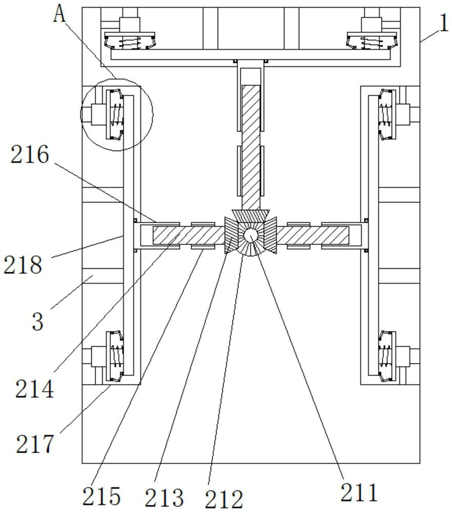
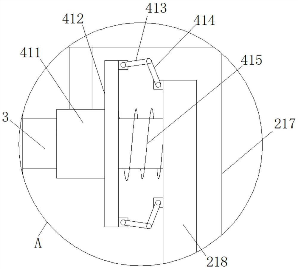
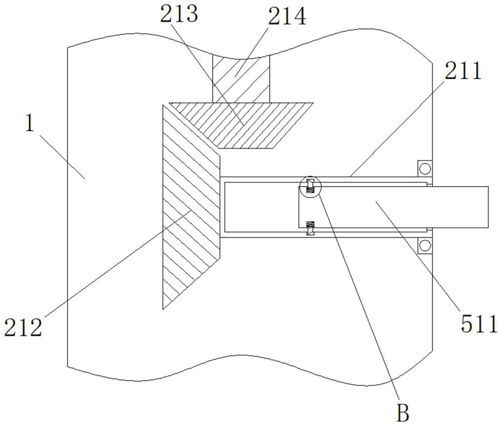
The invention relates to a lateral stretching-free tie bar device for an external wall panel. The device comprises an external wall panel body, a plurality of sets of tie bars horizontally distributedat the top end of the external wall panel body and vertically distributed at the left side and the right side of the external wall panel body, and a pushing device for driving the tie bars to stretchout of the external wall panel body. The pushing device comprises a rotating rod, a driving gear, driven gears, lead screws, a sleeve, a movable sleeve and a movable plate; the rotating rod is rotationally connected with the inner wall of the front end of the external wall panel body, and the rear end of the rotating rod is fixedly connected with the driving gear; the driving gear can be driven to rotate through the rotation of the rotating rod, then the three sets of driven gears rotate, at the moment, the three sets of lead screws rotate, the movable sleeve and the movable plate are drivento move towards the outer side of the external wall plate under the action of threads, and then the three sets of tie bars are driven to move towards the outer side. According to the lateral stretching-free tie bar device for the external wall panel, the situation that a mold for the reproduction of the external wall panels do not need to be slotted, the overall strength of the mold is improved, and operation is more convenient when the mold is bound with a cast-in-place wall column tie bar.

Description

technical field [0001] The invention relates to the technical field of installation of exterior wall panels, in particular to a lateral stretch-free reinforcement device for exterior wall panels. Background technique [0002] When the exterior wall panel is installed, the lateral tension bars of the wall panel are continuously stretched. This method requires opening the mold during the production process, which reduces the overall strength of the mold, and at the same time reduces the mold supply rate and mold turnover rate. And when the tension bars extend out of the wallboard, it is easy to affect the binding of the wallboard and the cast-in-place wall column reinforcement, which is not conducive to the on-site construction effect and reduces the service efficiency of the device. Contents of the invention [0003] The technical problem to be solved by the present invention is to provide a lateral stretch-free tensioning device for exterior wall panels to solve the need f...

Claims


Application Information

Patent Timeline
Patent Type & Authority Applications(China)
IPC IPC(8): E04F13/076E04G21/16
CPCE04F13/0866E04G21/167
Inventor 张经明颜学金黄纪文
Owner 湖南泽坤建筑设计有限公司
Learn More