Shield tunnel synchronous grouting similar model testing system and method

A technology of simultaneous grouting and similar models, applied in tunnels, tunnel linings, teaching models, etc., can solve problems such as the inability to directly observe the movement of grout, filling and distribution status, quantitative evaluation, and complex impacts, so as to reduce the impact of environmental disturbances. , Guarantee early stability, improve the effect of structural stability

Active Publication Date: 2021-01-29
CHINA RAILWAY 19TH BUREAU GRP RAIL TRANSIT ENG +1
View PDF5 Cites 5 Cited by
  • Summary
  • Abstract
  • Description
  • Claims
  • Application Information

AI Technical Summary

Problems solved by technology

Therefore, it is necessary to adopt the method of synchronous grouting during construction to effectively fill the annular space at the tail of the shield, improve the structural stability of the shield tunnel, and reduce the impact of environmental disturbance during construction. Flow and seepage in the soil outside the ring, the movement, filling and distribution of the slurry cannot be directly observed
Problems existing in synchronous grouting: i) The influence of formation characteristics, engineering geology and hydrogeology is complex; ii) The concealment of grout filling and the uncertainty of grouting effect, so there is a large degree of blindness in grouting design and construction iii) There is no scientific and accurate evaluation method for the relevance and sensitivity of synchronous grouting grout to the environment, and it is difficult to quantitatively evaluate the effect of grouting during construction and its environmental impact by theoretical (or numerical calculation) methods

Method used


Image

  • Shield tunnel synchronous grouting similar model testing system and method
  • Shield tunnel synchronous grouting similar model testing system and method
  • Shield tunnel synchronous grouting similar model testing system and method

Examples


Embodiment Construction

[0033] The following will clearly and completely describe the technical solutions in the embodiments of the present invention with reference to the accompanying drawings in the embodiments of the present invention. Obviously, the described embodiments are only some, not all, embodiments of the present invention. Based on the embodiments of the present invention, all other embodiments obtained by persons of ordinary skill in the art without making creative efforts belong to the protection scope of the present invention.

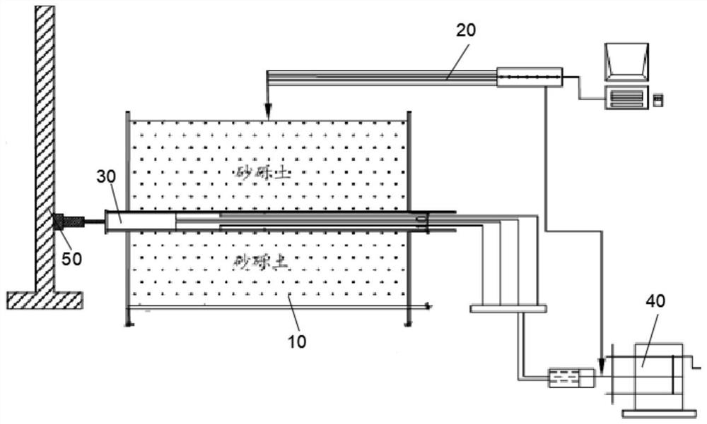
[0034] refer to Figure 1-4 , a shield tunnel synchronous grouting similar model test method, comprising: a test box 10, a data acquisition system 20 connected to the top surface of the test box 10, a construction simulation system 30 running through the test box 10, and the construction simulation system The grouting system 40 connected by the system 30 and the propulsion system 50 used to push the construction simulation system 30, and gravel soil is placed ...


PUM


Abstract

The invention discloses a shield tunnel synchronous grouting similar model testing method. A test box, a data acquisition system connected to the top surface of the test box, a construction simulationsystem penetrating through the test box, a grouting system communicating with the construction simulation system, and a propelling system used for propelling the construction simulation system are included. Gravel soil is placed in the test box; the propelling system comprises a hydraulic jack and a counter-force frame fixedly connected with one end of the hydraulic jack; the counter-force frameis fixed on the bottom face; the construction simulation system comprises a first long pipeline 32 pre-embedded in the test box and a second short pipeline 31 connected with the first long pipeline 32in a sleeving manner; the data acquisition system comprises a static strain gauge, displacement detection sensors and miniature pressure sensors; and the displacement detection sensors and the miniature pressure sensors are connected with the static strain gauge. According to the method, conditions of any soft soil stratum, geometric scale of a tunnel, construction excavation process and synchronous grouting parameters are effectively simulated, and the flow and permeation of slurry are effectively observed.

Description

technical field [0001] The invention relates to the technical field of synchronous grouting, in particular to a similar model test method for synchronous grouting of a shield tunnel. Background technique [0002] During shield construction, when the pipe ring is installed and the shield tail is moved forward, there will inevitably be a 30-50 mm annular gap between the soil and the tunnel structure, which will induce an increase in the loss rate of the surrounding stratum soil and cause soil disturbance displacement and adverse effects on the environment. Therefore, it is necessary to adopt the method of synchronous grouting during construction to effectively fill the annular space at the tail of the shield, improve the structural stability of the shield tunnel, and reduce the impact of environmental disturbance during construction. The flow and seepage in the soil outside the ring cannot directly observe the movement, filling and distribution of the slurry. Problems existi...

Claims


Application Information

Patent Timeline
Patent Type & Authority Applications(China)
IPC IPC(8): E21D9/06E21D11/10E21F17/00E21F17/18G09B25/04
CPCE21D9/0607E21D11/10E21F17/00E21F17/18G09B25/04
Inventor 杨晓虎王颖轶李涛张洪斌黄醒春殷雪峰罗鸣唐旭李健那迪张家硕
Owner CHINA RAILWAY 19TH BUREAU GRP RAIL TRANSIT ENG
Why Eureka
Try Eureka