Intelligent laser tester

A tester and laser technology, applied in the field of measurement, can solve the problems of increasing the difficulty of work and inconvenient operation of the staff, and achieve the effect of reducing the difficulty of work, easy operation and improving the accuracy of the test

Active Publication Date: 2021-01-29
WENZHOU UNIVERSITY
View PDF6 Cites 0 Cited by
  • Summary
  • Abstract
  • Description
  • Claims
  • Application Information

AI Technical Summary

Problems solved by technology

[0004] The present invention intends to provide an intelligent laser tester to solve the problem that the current method of adjust

Method used


Image

  • Intelligent laser tester
  • Intelligent laser tester
  • Intelligent laser tester

Examples


Embodiment 1

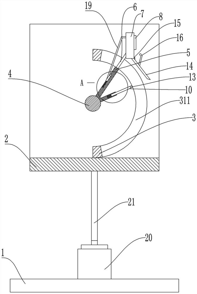
[0035] Basic as attached figure 1 , attached figure 2 , attached image 3 And attached Figure 4 Shown: an intelligent laser tester, including a base 1 and a lifting platform 2, the base 1 is provided with a lifting mechanism for driving the lifting platform 2 up and down, and the lifting mechanism includes a cylinder 20 symmetrically fixed on the base 1 along the center line of the base 1 , a vertical block 21 affixed to the output shaft of the cylinder 20, and the free end of the vertical block 21 is affixed to the bottom of the lifting platform 2.

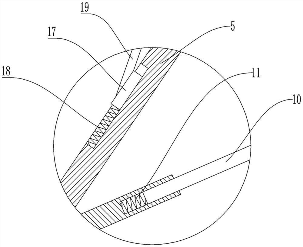
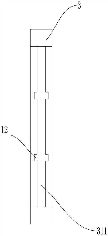
[0036]The lifting platform 2 is concave, and the lifting platform 2 is fixedly connected with an arc-shaped block 3, and the arc-shaped block 3 is provided with an arc-shaped hole 311; shaft setting; the arc surface of the rotating shaft 4 is fixedly connected with the adjusting rod 5, and the free end of the adjusting rod 5 is fixedly connected with the guide block 6, and the guide block 6 is slidingly connected with the ar...

Embodiment 2

[0046] Basic as attached Figure 5 As shown, the structure and implementation of Embodiment 2 are basically the same as Embodiment 1, the difference is that: the base 1 is fixed with a transverse plate 22, and the transverse plate 22 is located between the lifting platform 2 and the base 1; the transverse plate 22 are symmetrically provided with a vertical hole and a transverse groove 23 along the center line of the transverse plate 22, and the distance between the two vertical holes is greater than the distance between the two transverse grooves 23; the vertical block 21 is slidingly connected with the vertical hole, and the transverse groove 23 The horizontal block 24 is slidingly connected inside; the horizontal plate 22 is vertically slidably connected with a rack 25 passing through the lifting platform 2, and the rack 25 is located between the two transverse grooves 23; The gear 26 of gear; The both sides of rack 25 are all hinged with linkage arm 27, and the free end of ...


PUM


Abstract

The invention relates to the technical field of measurement, and discloses an intelligent laser tester. The intelligent laser tester comprises a base and further comprises a lifting table, wherein a lifting mechanism used for driving the lifting table to ascend and descend is arranged on the base; an arc-shaped block is arranged on the lifting table, and an arc-shaped hole is formed in the arc-shaped block; a rotating shaft is rotationally connected to the lifting table, and the arc-shaped block and the rotating shaft are coaxially arranged; an adjusting rod is arranged on the arc-shaped surface of the rotating shaft, a guide block is arranged on the adjusting rod and connected with the arc-shaped hole in a sliding manner, and a limiting mechanism for the intelligent laser tester is arranged at the free end of the guide block; the width of the adjusting rod is larger than that of the arc-shaped hole, and the end, close to the guide block, of the adjusting rod abuts against the arc-shaped block. The intelligent laser tester further comprises a positioning mechanism which is used for positioning the rotating shaft. According to the scheme, the problems that the working difficulty ofworkers is increased and the operation is very inconvenient due to the existing mode of adjusting the height of the intelligent laser tester are mainly solved.

Description

technical field [0001] The invention relates to the field of measurement technology. Background technique [0002] Laser rangefinder, also called intelligent laser tester, is an instrument that uses a certain parameter of modulated laser to accurately measure the distance of the target. The pulse type intelligent laser tester emits a beam or a sequence of short pulse laser beams to the target when it is working, and the photoelectric element receives the laser beam reflected by the target, and the timer measures the time from the launch to the reception of the laser beam, and calculates The distance from the meter to the target. [0003] At present, before the smart laser tester is used, it is necessary to place a bracket on the ground, and then fix the smart laser tester on the bracket for testing; in actual use, due to the fixed height of the bracket, the smart laser tester fixed on the bracket The height of the laser tester is fixed. When testing a higher position, the ...

Claims


Application Information

Patent Timeline
IPC IPC(8): F16M11/04F16M11/16F16M11/18F16M11/28G01S7/481G01S17/10
CPCF16M11/04F16M11/046F16M11/16F16M11/18F16M11/28G01S7/481G01S17/10Y02E10/50
Inventor 朱德华陈明绍张书平秦渊李峰平
Owner WENZHOU UNIVERSITY
Why Eureka
Try Eureka