
Two-stage surface air cooler for fresh air dehumidification equipment

A fresh air dehumidification and surface cooler technology, which is applied in lighting and heating equipment, applications, household heating, etc., can solve problems such as unsatisfactory use effect, inconvenient suspension installation, and inability to guide and discharge dripping liquid, etc., to ensure suspension Hanging installation stability, ensuring the protection effect, increasing the effect of suspension function

Pending Publication Date: 2021-01-29
能邦(苏州)换热器有限公司
View PDF0 Cites 0 Cited by
  • Summary
  • Abstract
  • Description
  • Claims
  • Application Information

AI Technical Summary

Problems solved by technology

[0006] The technical problem to be solved by the present invention is: to provide a two-stage surface cooler for fresh air dehumidification equipment to solve the problem that the existing two-stage surface cooler cannot guide and discharge the dripping liquid , it is not convenient for suspension installation and the problem of unsatisfactory use effect

Method used


Image

  • Two-stage surface air cooler for fresh air dehumidification equipment
  • Two-stage surface air cooler for fresh air dehumidification equipment
  • Two-stage surface air cooler for fresh air dehumidification equipment

Examples


Embodiment Construction

[0028] The present invention is described in detail below in conjunction with accompanying drawing:

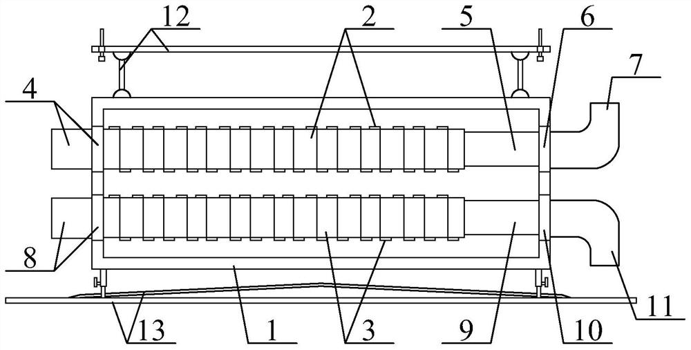
[0029] as attached figure 1 And attached figure 2 As shown, a two-stage surface cooler for fresh air dehumidification equipment according to the present invention includes a fresh air dehumidifier housing 1, a primary surface cooler 2, a secondary surface cooler 3, a primary outlet pipe 4, and a primary Water inlet pipe 5, primary pipe joint 6, primary water inlet elbow 7, secondary water outlet pipe 8, secondary water inlet pipe 9, secondary pipe joint 10, secondary water inlet elbow 11, suspension and stable support structure 12 And the adjustable drip deflector protection plate structure 13, the upper and lower parts on the left side of the fresh air dehumidifier shell 1 are connected with the first-level surface cooler 2 and the second-level surface cooler 3 by parallel bolts; the fresh air dehumidifier There is a first-stage water outlet pipe 4 threadedly connected to ...


PUM


Abstract

The invention discloses a two-stage surface air cooler for fresh air dehumidification equipment. The two-stage surface air cooler comprises a fresh air dehumidifier shell, a first-stage surface air cooler, a second-stage surface air cooler, a first-stage water outlet pipe, a first-stage water inlet pipe, a first-stage pipe joint, a first-stage water inlet bent pipe, a second-stage water outlet pipe, a second-stage water inlet pipe, a second-stage pipe joint, a second-stage water inlet bent pipe, a suspended stabilizing bracket structure and an adjustable dropping liquid flow guiding protectiveplate structure, wherein the first-stage surface cooler and the second-stage surface cooler are connected to the upper part and the lower part of the left side of the interior of the fresh air dehumidifier shell in parallel through bolts; and a first-stage water outlet pipe is in threaded connection with an outlet in the upper left wall of the inner side of the fresh air dehumidifier shell. Through the arrangement of a suspension frame, mounting holes, expansion bolts, suspension rings, suspension supporting rods and pull rings, the suspension function can be improved, and the suspension mounting stability is guaranteed; and due to the arrangement of a protective bottom plate and dropping liquid flow deflectors, dropping liquid can be guided out in real time, and the problem of equipmentdamage or environmental pollution is avoided.

Description

technical field [0001] The invention belongs to the technical field of surface coolers, in particular to a two-stage surface cooler for fresh air dehumidification equipment. Background technique [0002] Dehumidification fresh air fan is a device that integrates fresh air, dehumidification and purification functions. It can provide two modes of fresh air and dehumidification according to the needs of customers at different time periods. At the same time, it has the function of purifying air during circulation and dehumidification, so that the air in the living space Fresh while achieving the right humidity. [0003] At present, the surface cooler, the full name of the surface cooler, its principle is to let the heat medium or refrigerant or refrigerant flow through the inner cavity of the metal pipe, and the air to be processed flows through the outer wall of the metal pipe for heat exchange to achieve heating or cooling of the air. Purpose. [0004] However, the existing ...

Claims


Application Information

Patent Timeline
Patent Type & Authority Applications(China)
IPC IPC(8): F24F3/14F24F5/00F24F7/00F24F13/20F24F13/30F24F13/32
CPCF24F3/14F24F5/0007F24F7/00F24F13/20F24F13/30F24F13/32F24F2003/144
Inventor 陆彩萍王兵陈庆飞
Owner 能邦(苏州)换热器有限公司
Learn More