A device for removing bone nails with convenient positioning

A bone nail, a convenient technology, applied in the field of medical devices, can solve the problems of inconvenient bone screw positioning, increase the workload of doctors, increase the pain of patients, etc., and achieve the effects of reducing the difficulty of surgery, improving the efficiency of nail removal, and being convenient to use

Inactive Publication Date: 2021-08-13
车军双
View PDF0 Cites 0 Cited by
  • Summary
  • Abstract
  • Description
  • Claims
  • Application Information

AI Technical Summary

Problems solved by technology

[0003] After the fracture is healed, the bone nail needs to be removed. However, the existing nail removal device is inconvenient to locate the bone nail, especially for a bone nail with a small size, such as a diameter of only one or two millimeters, which is extremely difficult to operate with the doctor's vision alone. Large, in the process of removing the nail, it is easy to repeatedly operate to remove the bone nail, which not only increases the pain of the patient, but also increases the workload of the doctor

Method used


Image

  • A device for removing bone nails with convenient positioning
  • A device for removing bone nails with convenient positioning
  • A device for removing bone nails with convenient positioning

Examples


Embodiment 1

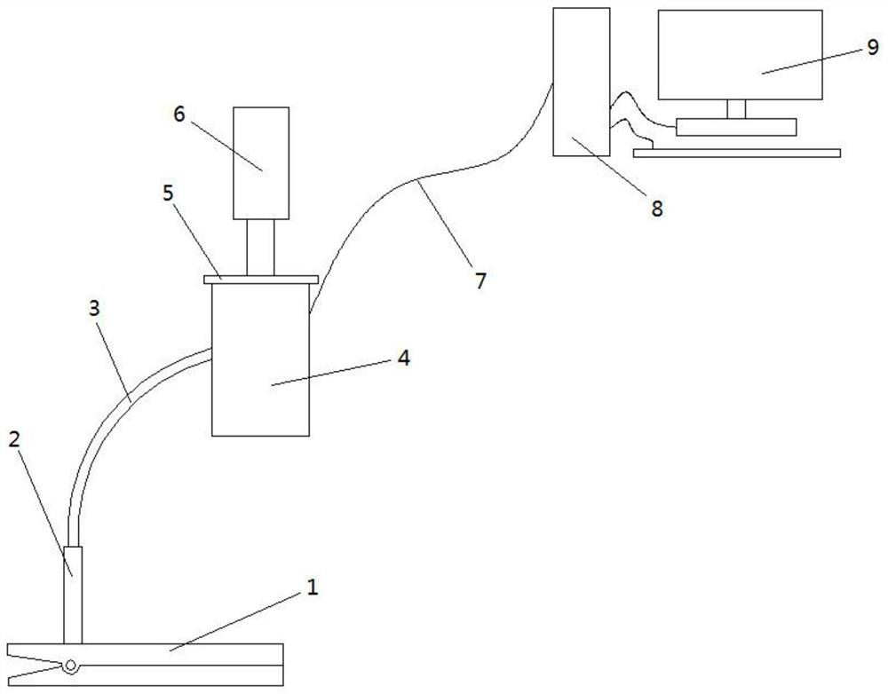
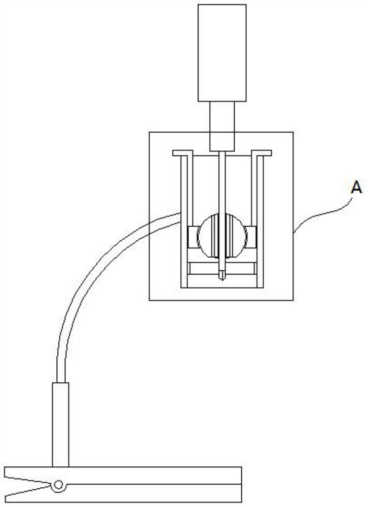
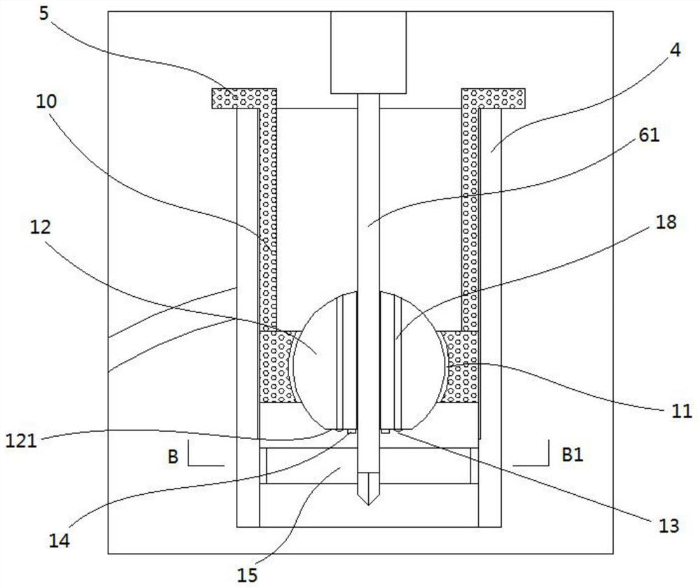
[0025] A conveniently positioned bone screw removal device, comprising an outer cylinder 4, an inner cylinder 10, and a screwdriver 6, the upper inner surface of the outer cylinder 4 is provided with internal threads, and the outer wall surface of the inner cylinder 10 is provided with external threads , the inner cylinder 10 is screwed into the outer cylinder 4, the top of the inner cylinder 4 is provided with an outwardly folded annular edge 5, and the bottom of the inner cylinder 4 is provided with a cylinder bottom 101, and the cylinder bottom 101 The middle part is provided with the spherical joint capsule 11 that runs through the upper and lower end surfaces, and the joint capsule 11 is provided with a joint ball 12, and the upper and lower ends of the joint capsule 12 extend out of the upper and lower ports of the joint capsule 11 respectively. The outer wall surface of the ball 12 is slidingly connected with the inner wall surface of the joint capsule 11. At the center ...

Embodiment 2

[0030] On the basis of Embodiment 1, this embodiment has made further improvements, specifically:

[0031] The micro camera 14 is a ring camera, and the ring camera is coaxial with the internally threaded hole.

Embodiment 3

[0033] On the basis of Embodiment 2, this embodiment has made further improvements, specifically:

[0034] There are four laser pointers 13, which are evenly distributed around the axis of the internally threaded hole at intervals of 90°;

[0035] An annular light strip 15 is also fixed on the inner wall surface of the outer cylinder 4 located below the inner cylinder 10;

[0036] The power of the laser pointer 13 is less than 5mw, and the outer wall of the outer cylinder 4 is also provided with a control switch for the laser pointer 13 .

[0037] In this embodiment, there are four laser pointers 13, such as Figure 5 As shown, when the four laser pointers project light spots 16 evenly distributed on the outer periphery of the nail head 17, the intersection of the two groups of laser pointer projected light spots 16 at opposite angles is the position of the nail head 17, which is the same as that of the screwdriver 6 The position of the head of the screwdriver is just opposi...


PUM


Abstract

A bone nail removal device for convenient positioning, which relates to the technical field of medical devices, including an outer cylinder, an inner cylinder, a screwdriver, a spherical joint capsule, a joint ball, an internal threaded hole, a plane area, a miniature camera, a laser pointer, an inner cylinder screw Connected in the outer cylinder, the bottom of the inner cylinder is provided with a joint capsule, the joint capsule is provided with a joint ball, the axis of the joint ball is provided with an internal threaded hole, the internal threaded hole is screwed with the blade of the screwdriver, and the lower end of the joint ball is provided with a The flat area is provided with a miniature camera and a laser pointer. The present invention is simple in structure and easy to use, and can quickly locate the nail head through the laser pointer when taking out the bone nail, which can effectively improve the efficiency of taking out the nail, especially for the bone nail with a small size. Instructing the operation through the computer screen, the doctor has a good operating experience, and the difficulty of the operation is greatly reduced.

Description

technical field [0001] The invention relates to the technical field of medical devices, in particular to a conveniently positioned bone nail removal device. Background technique [0002] A fracture is a break in the integrity and continuity of a bone. At present, for patients with obvious displacement and needing open reduction and internal fixation, the bone fragments at the fracture site are usually re-reset and fixed with steel plates and bone screws, so that the dislocated bone fragments are tightly connected again under the action of the plate screw system Together, after a long period of postoperative growth, the broken bone fragments grow new calluses and heal together again. [0003] After the fracture is healed, the bone nail needs to be removed. However, the existing nail removal device is inconvenient to locate the bone nail, especially for a bone nail with a small size, such as a diameter of only one or two millimeters, which is extremely difficult to operate wi...

Claims


Application Information

Patent Timeline
Patent Type & Authority Patents(China)
IPC IPC(8): A61B17/92A61B17/90
CPCA61B17/92A61B17/90
Inventor 车军双其他发明人请求不公开姓名
Owner 车军双
Why Eureka
Try Eureka