External liquid dressing equipment for dermatological department
A liquid dressing and dermatology technology, applied in the field of external liquid dressing equipment, can solve the problems of time and energy, waste of liquid medicine, etc., and achieve the effect of preventing waste, preventing self-flowing waste, and preventing cross-infection
- Summary
- Abstract
- Description
- Claims
- Application Information
AI Technical Summary
Problems solved by technology
Method used
Image

Examples
Embodiment 1
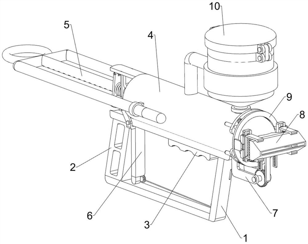
[0031] A topical liquid dressing device for use in dermatology, such as figure 1 , image 3 , Figure 4 ,and Figure 7 As shown, it includes a bracket 1, a handle 2, a hand rest block 3, a dressing bucket mechanism 4 and a material pushing mechanism 5, the left part of the bracket 1 is connected with the handle 2, and the upper right side of the bracket 1 is connected with a hand rest block 3, A dressing barrel mechanism 4 is installed on the top of the support 1, and a pushing mechanism 5 is installed on the dressing barrel mechanism 4.
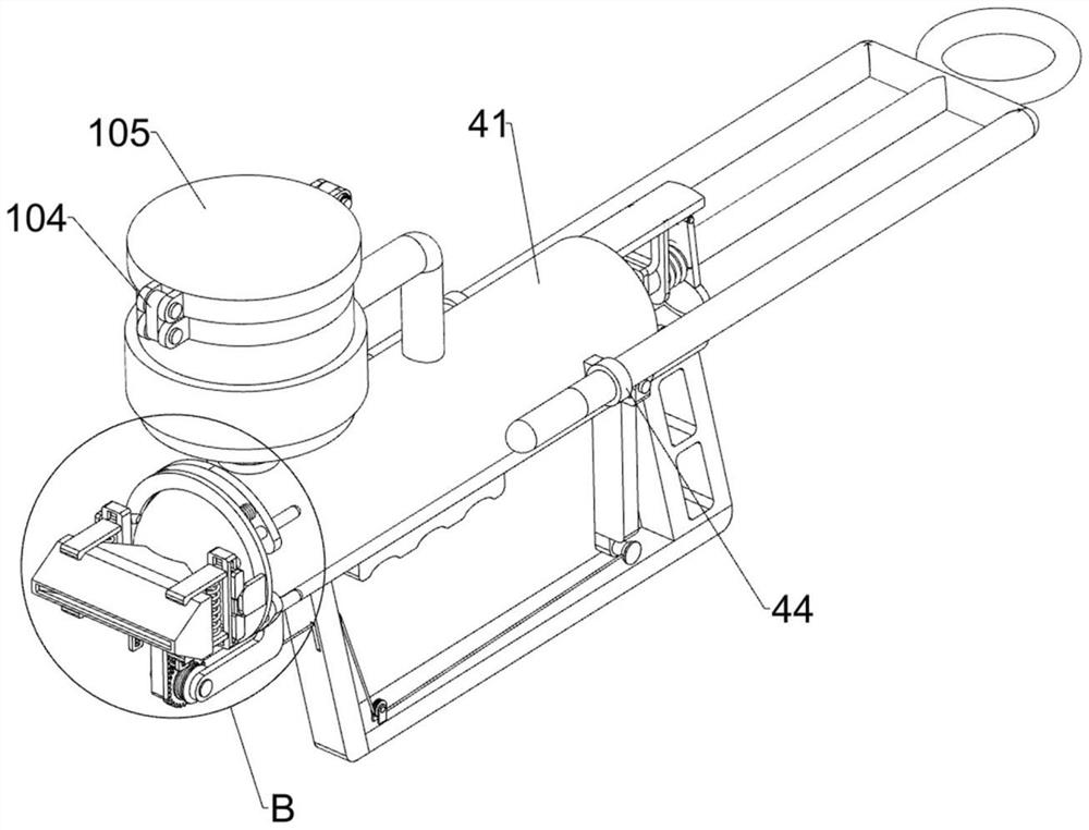
[0032] The dressing barrel mechanism 4 includes a cylinder 41, an arc-shaped gathering tube 42, a discharge nozzle 43 and a guide sleeve 44. The top of the support 1 is connected with the cylinder 41, and the right side of the cylinder 41 is connected with an arc-shaped gathering tube 42, and the arc gathers A discharge nozzle 43 is connected to the right side of the pipe 42 , and two guide sleeves 44 are connected symmetrically to the le...
Embodiment 2
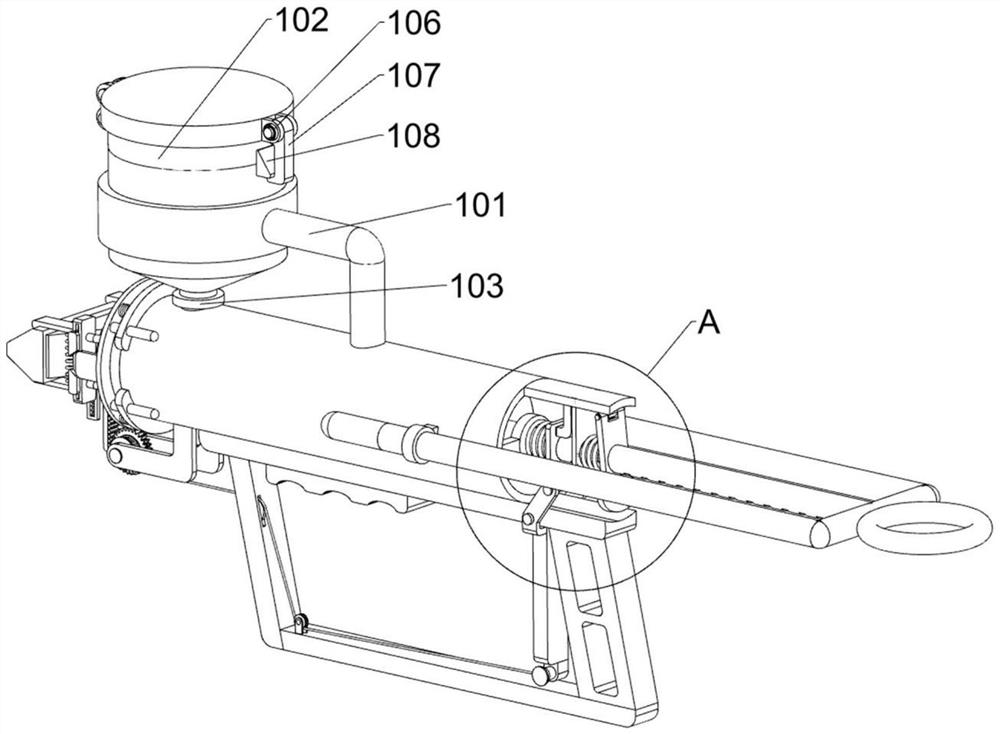
[0036] On the basis of Example 1, such as figure 1 and Figure 6As shown, the injection control mechanism 6 is also included, and the injection control mechanism 6 includes a fixed ring frame 61, a mounting plate 62, a block 63, a first clamping plate 64, a first spring 65, a fixed shaft 66, and a control handle frame 67. Push rod 68, the second clamping plate 69 and the second spring 610. The left side of the inner wall of the cylinder body 41 is connected with a fixed ring frame 61. The fixed ring frame 61 is slidingly connected with the slotted rod 51. There is a mounting plate 62, the bottom of the mounting plate 62 is connected with a stopper 63, the slotted bar 51 is slidably connected with a first clamping plate 64, the first clamping plate 64 cooperates with the groove of the slotted bar 51, the first clamping plate 64 and The stopper 63 is in contact with each other, the first spring 65 is connected between the first clamp 64 and the fixed ring frame 61, the upper si...
Embodiment 3
[0039] On the basis of Example 2, such as figure 1 and Figure 5 Shown, also include leak-proof mechanism 7, leak-proof mechanism 7 includes sliding baffle plate 71, guide frame 72, the 3rd spring 73, rack frame 74, fixed frame 75, transmission gear 76, reel 77, steel The cable 78, the first pulley frame 79, the second pulley frame 710 and the mounting seat 711, the bottom of the discharge nozzle 43 are symmetrically connected with two guide frames 72, and the two guide frames 72 are slidably connected with a sliding baffle plate 71 , the sliding baffle 71 is slidably connected to the discharge nozzle 43, the third spring 73 is connected between the sliding baffle 71 and the guide frame 72, the bottom of the sliding baffle 71 is connected to the rack frame 74, and the bottom right side of the cylinder 41 is connected to There is a fixed mount 75, the fixed mount 75 is rotatably connected with a transmission gear 76, the transmission gear 76 is engaged with the rack frame 74, ...
PUM
 Abstract
Description
Claims
Application Information
 - R&D
- Intellectual Property
- Life Sciences
- Materials
- Tech Scout
- Unparalleled Data Quality
- Higher Quality Content
- 60% Fewer Hallucinations
Browse by: Latest US Patents, China's latest patents, Technical Efficacy Thesaurus, Application Domain, Technology Topic, Popular Technical Reports.
© 2025 PatSnap. All rights reserved.Legal|Privacy policy|Modern Slavery Act Transparency Statement|Sitemap|About US| Contact US: help@patsnap.com