Device and method for absorbing gas

An absorption device and a technology for absorbing gas, which are applied in separation methods, chemical instruments and methods, and separation of dispersed particles, can solve problems such as large errors in manual control and monitoring, safety accidents and environmental pollution, and increase labor costs. Effect

Active Publication Date: 2021-02-02
SINOPEC ENG +1
View PDF8 Cites 0 Cited by
  • Summary
  • Abstract
  • Description
  • Claims
  • Application Information

AI Technical Summary

Problems solved by technology

[0007] Existing gas absorbing devices usually absorb intermittently discharged gas through manual control and monitoring, which has large errors in manual control and monitoring, increases labor costs, and also has the risk of misoperation, which is likely to cause safety accidents and environmental pollution

Method used


Image

  • Device and method for absorbing gas
  • Device and method for absorbing gas

Examples


Embodiment 1

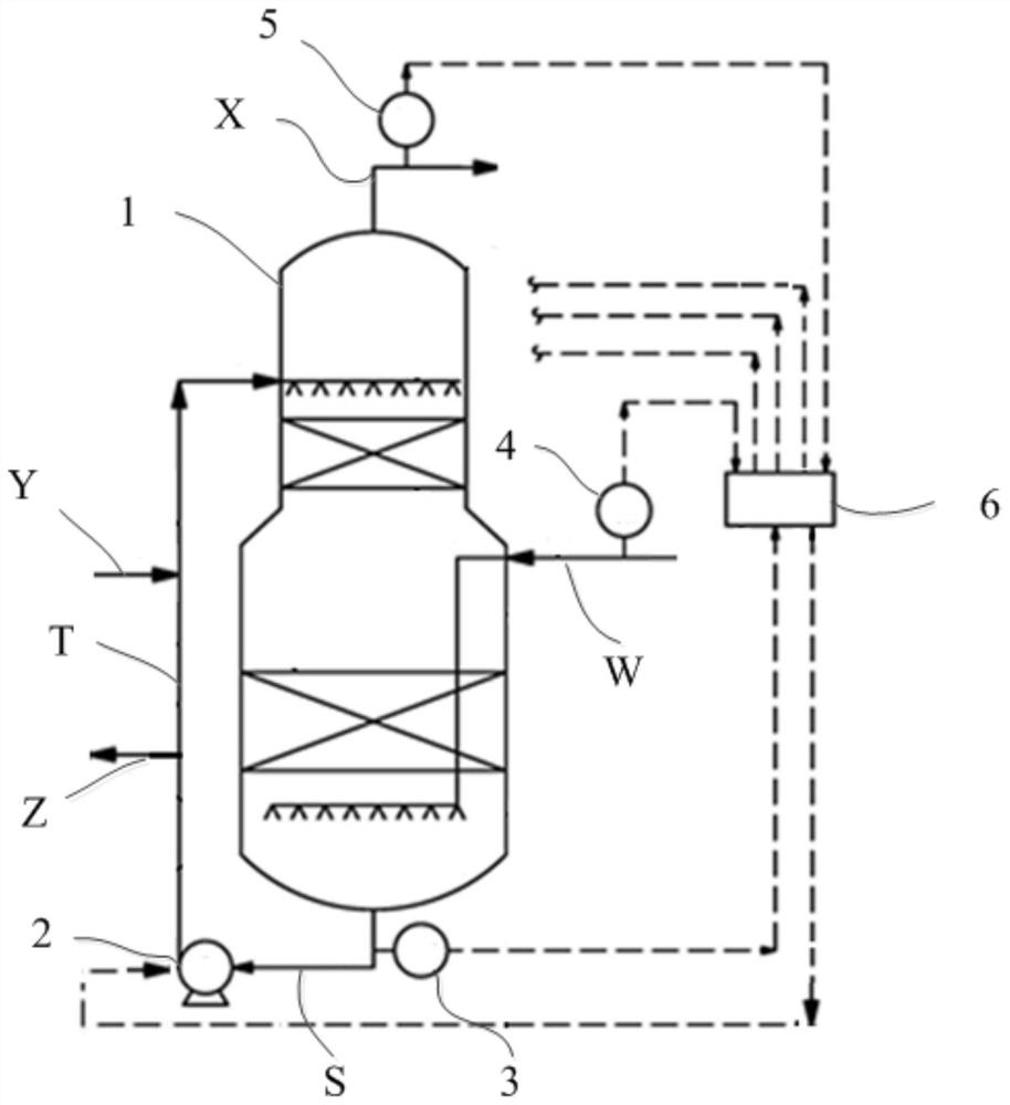
[0083] This embodiment provides a device for absorbing gas. See figure 1 , figure 1 A schematic diagram of a device for absorbing gas provided by the present invention is shown. Such as figure 1 As shown, the device includes: absorption device 1, circulating pump 2, component analyzer 3, inlet analyzer 4, outlet analyzer 5, automatic control system 6, circulating liquid outlet pipeline S, circulating liquid inlet pipeline T, gas inlet Pipeline W, gas outlet pipe X, liquid inlet pipe Y, and liquid discharge pipe Z; the liquid inlet and outlet ends of the circulation pump 2 communicate with the absorption device 1 through the circulation liquid outlet pipe S and the circulation liquid inlet pipe T respectively; The sub-analyzer 3 is set on the circulating liquid outlet pipeline S; the gas inlet pipeline W, the gas outlet pipeline X, the liquid inlet pipeline Y, and the liquid discharge pipeline Z are all connected with the absorption device 1; the inlet analyzer 4 is arranged...

Embodiment 2

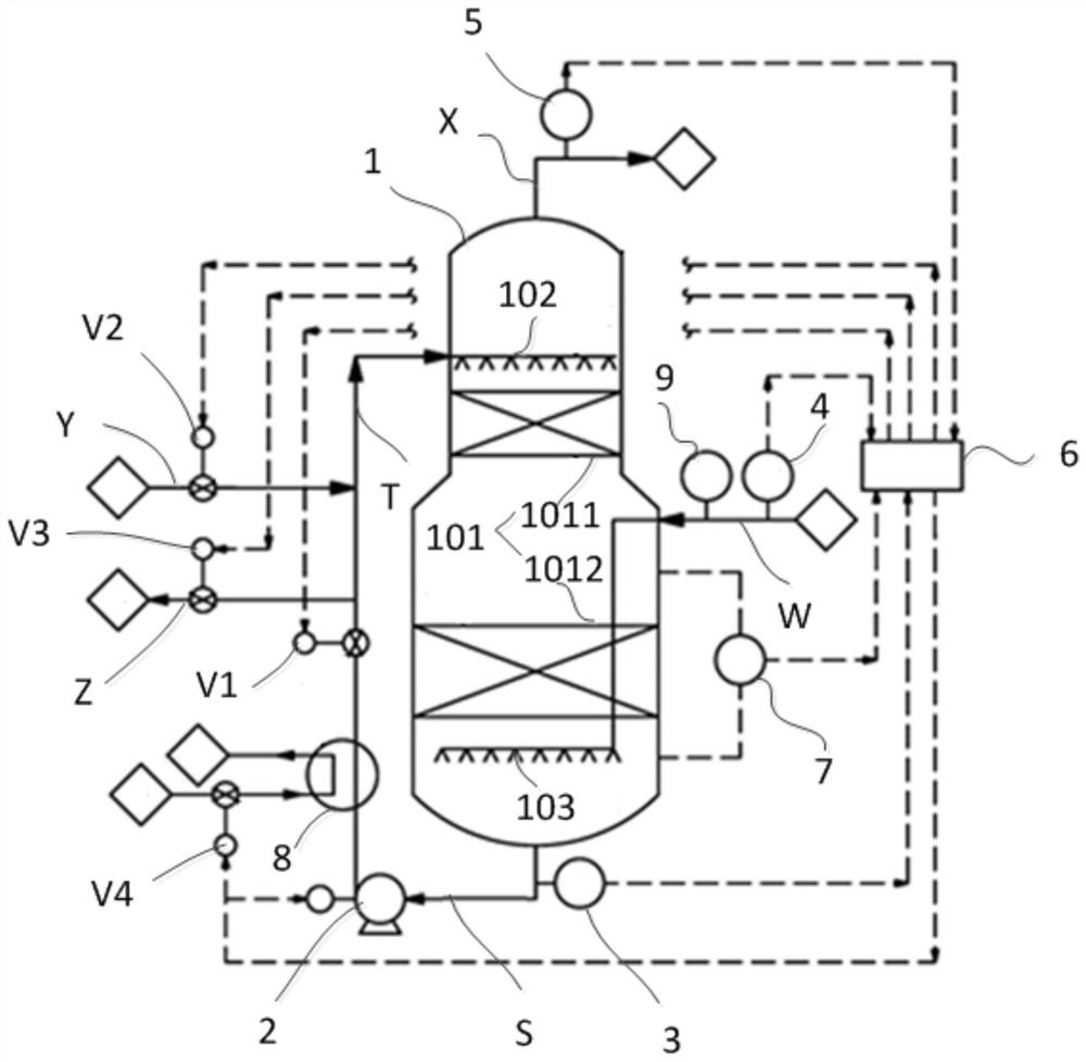
[0086] This embodiment provides a device for absorbing gas. See figure 2 , figure 2 A schematic diagram of another device for absorbing gas provided by the present invention is shown. Such as figure 2 As shown, the device includes: absorption device 1, circulating pump 2, component analyzer 3, inlet analyzer 4, outlet analyzer 5, automatic control system 6, liquid level gauge 7, cooler 8, thermometer, circulating liquid outlet Pipeline S, circulating liquid inlet pipe T, gas inlet pipe W, gas outlet pipe X, liquid inlet pipe Y, liquid discharge pipe Z, first valve V1, second valve V2, third valve V3, and fourth valve V4.

[0087] The liquid inlet end and the liquid outlet end of the circulation pump 2 communicate with the absorption device 1 through the circulation liquid outlet pipeline S and the circulation liquid inlet pipeline T respectively; the component analyzer 3 is arranged on the circulation liquid outlet pipeline S; the gas inlet pipe W, the gas The outlet pi...

Embodiment 3

[0089] This embodiment provides a method for absorbing gas. See figure 1 , the method includes the following steps:

[0090] The gas enters the absorption device 1 through the gas inlet pipe W; the inlet analyzer 4 detects that the gas content in the absorption device increases, and sends the result of the gas content increase to the automatic control system 6, and the automatic control system 6 receives the result, And control the liquid inlet pipe Y to deliver the absorption liquid to the absorption device 1 to absorb the gas.

[0091] The circulating pump 2 sucks part of the liquid into the circulating liquid outlet pipe S, and returns to the absorption device 1 through the circulating liquid inlet pipe T.

[0092] The component analyzer 3 detects the liquid in the circulating liquid outlet pipe S, and sends the detected result to the automatic control system 6, and the automatic control system 6 receives the result, and controls the Y-direction absorption through the liq...


PUM


Abstract

The invention belongs to the technical field of gas treatment, and relates to a device and a method for absorbing gas. The device comprises an absorption device, a circulating pump, a component analyzer, an inlet analyzer, an outlet analyzer, an automatic control system, a circulating liquid outlet pipeline, a circulating liquid inlet pipeline, a gas inlet pipeline, a gas outlet pipeline, a liquidinlet pipeline and a liquid discharge pipeline. The liquid inlet end and the liquid outlet end of the circulating pump are respectively communicated with the absorption device through the circulatingliquid outlet pipeline and the circulating liquid inlet pipeline; the component analyzer is arranged on the circulating liquid outlet pipeline; the inlet analyzer is arranged on the gas inlet pipeline; the outlet analyzer is arranged on the gas outlet pipeline; the inlet analyzer, the component analyzer and the outlet analyzer are respectively used for transmitting detected results to the automatic control system; and the automatic control system is used for controlling the circulating pump to be started according to the result, controlling liquid to enter the absorption device or liquid in the absorption device to be discharged, and controlling the circulating amount of the circulating pump. The device can automatically and accurately control the gas absorption process.

Description

technical field [0001] The invention belongs to the technical field of gas treatment, and more specifically relates to a device and method for absorbing gas. Background technique [0002] The process of transferring one or more components of a gas mixture from the gas phase to the liquid phase. Gas absorption is a commonly used unit operation in chemical production. According to the absorption properties, it can be divided into two categories: chemical absorption and physical absorption. Gas absorption is widely used in technical fields such as synthetic ammonia, petrochemical industry and waste gas treatment. [0003] Chemical absorption refers to the absorption process in which the absorbent and the absorbent have obvious chemical reactions during the absorption process. For chemical absorption, the mass transfer mechanism of solute from the main body of the gas phase to the gas-liquid interface is exactly the same as that of physical absorption, and the complexity lies ...

Claims


Application Information

Patent Timeline
Patent Type & Authority Applications(China)
IPC IPC(8): B01D53/14B01D53/18
CPCB01D53/18B01D53/1412
Inventor 裴嘉宁张建华徐垚杨照陈璐刘为钢
Owner SINOPEC ENG
Why Eureka
Try Eureka