Button surface heat treatment forming equipment

A technology of surface heat treatment and forming equipment, which is applied in heat treatment equipment, heat treatment furnaces, presses for material forming, etc., can solve the problems of low work efficiency, laborious, troublesome, etc., and achieve the effect of high work efficiency

Pending Publication Date: 2021-02-02
李艾清
View PDF6 Cites 0 Cited by
  • Summary
  • Abstract
  • Description
  • Claims
  • Application Information

AI Technical Summary

Problems solved by technology

[0005] In order to overcome the disadvantages that after pressing the surface texture of the button, people need to take it off by hand, which is troublesome, the work efficiency is low, and it also requires people to put the button into the machine continuously by hand, which is relatively laborious, the tech

Method used


Image

  • Button surface heat treatment forming equipment
  • Button surface heat treatment forming equipment
  • Button surface heat treatment forming equipment

Examples


Embodiment 1

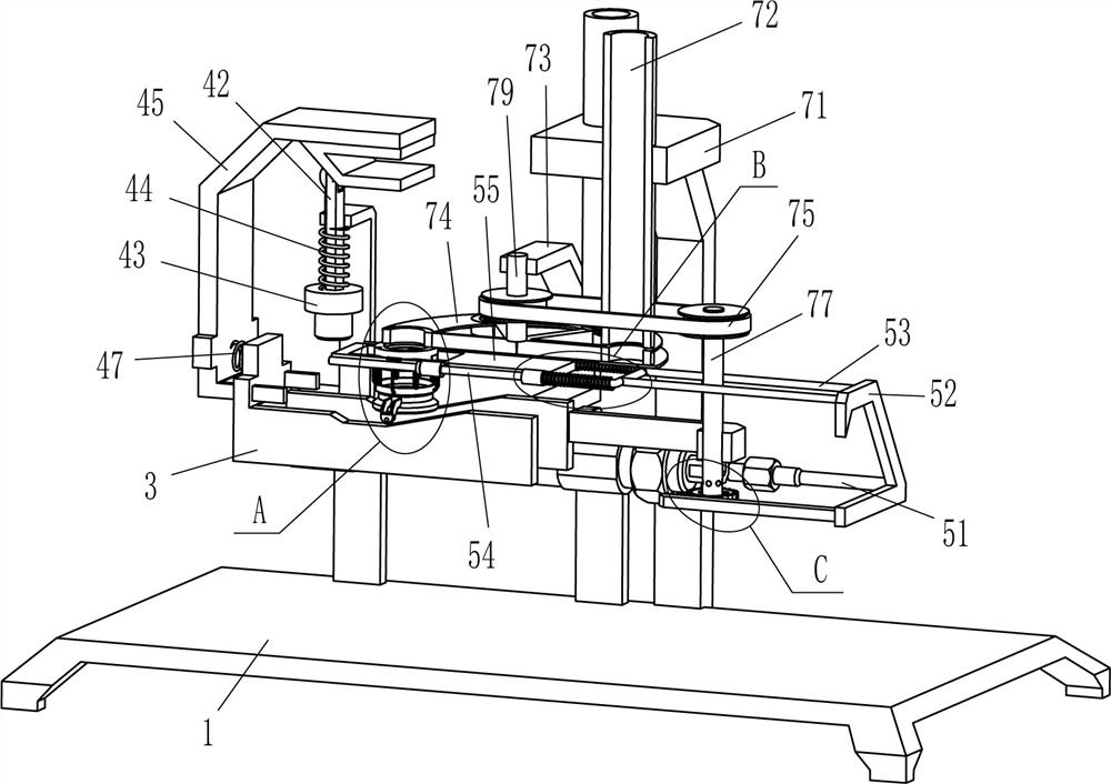
[0027] A button surface heat treatment forming equipment, such as figure 1 , figure 2 , image 3 , Figure 5 and Figure 6 As shown, it includes a base 1, an L-shaped plate 2, a special-shaped plate 3, a stamping mechanism 4, a driving mechanism 5 and a placement mechanism 6. Two L-shaped plates 2 and four A special-shaped plate 3 is fixedly connected between the inner ends of the L-shaped plates 2, and the left part of the special-shaped plate 3 is provided with a stamping mechanism 4, and a drive mechanism 5 is provided between the inner side of the four L-shaped plates 2 and the special-shaped plate 3, and the drive mechanism 5 is connected to the special-shaped plate 3. The stamping mechanism 4 cooperates, and the driving mechanism 5 is provided with a placement mechanism 6, which contacts and cooperates with the special-shaped plate 3.

[0028]Stamping mechanism 4 includes n-type plate 41, movable slide bar 42, stamping head 43, first spring 44, special-shaped slide ...

Embodiment 2

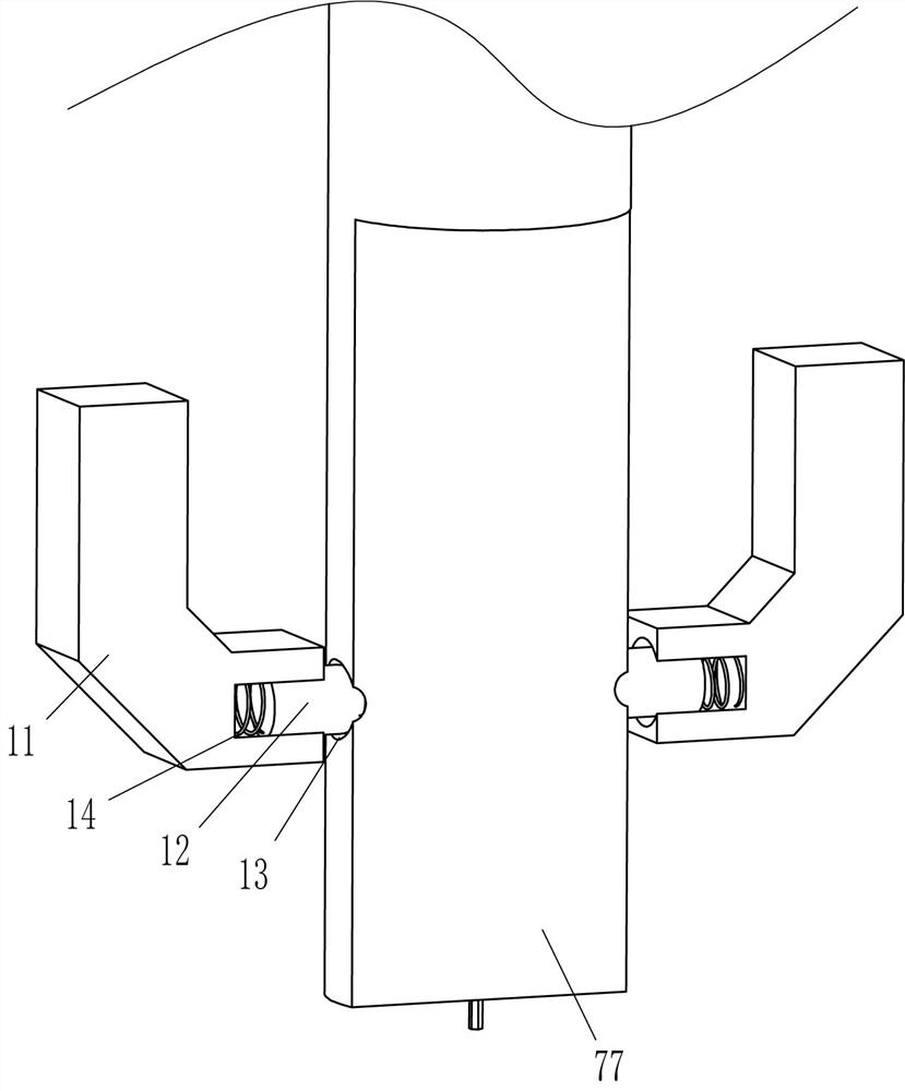
[0036] On the basis of Example 1, such as figure 1 , figure 2 and Figure 7 As shown, a blanking mechanism 7 is also included, and the blanking mechanism 7 includes a fixed frame 71, a discharge pipe 72, a mounting frame 73, a porous placement plate 74, a transmission assembly 75, a mounting block 76, a rotating rod 77, and a gap plate 78 , rotating shaft 79, ratchet wheel 710 and ratchet bar 711, mounting frame 73 is fixedly connected between the upper part of the right side of the front and rear sides of the special-shaped plate 3, the rotating shaft 79 is connected in the middle of the mounting frame 73 top, and the bottom end of the rotating shaft 79 is fixedly connected There is a porous disc 74, and a notch disc 78 is fixedly connected between the upper and lower sides of the mounting frame 73. The gap of the notch disc 78 is matched with the annular block 61, and the top of the notch disc 78 is in contact with the bottom of the porous disc 74. 3. A mounting block 76 ...

Embodiment 3

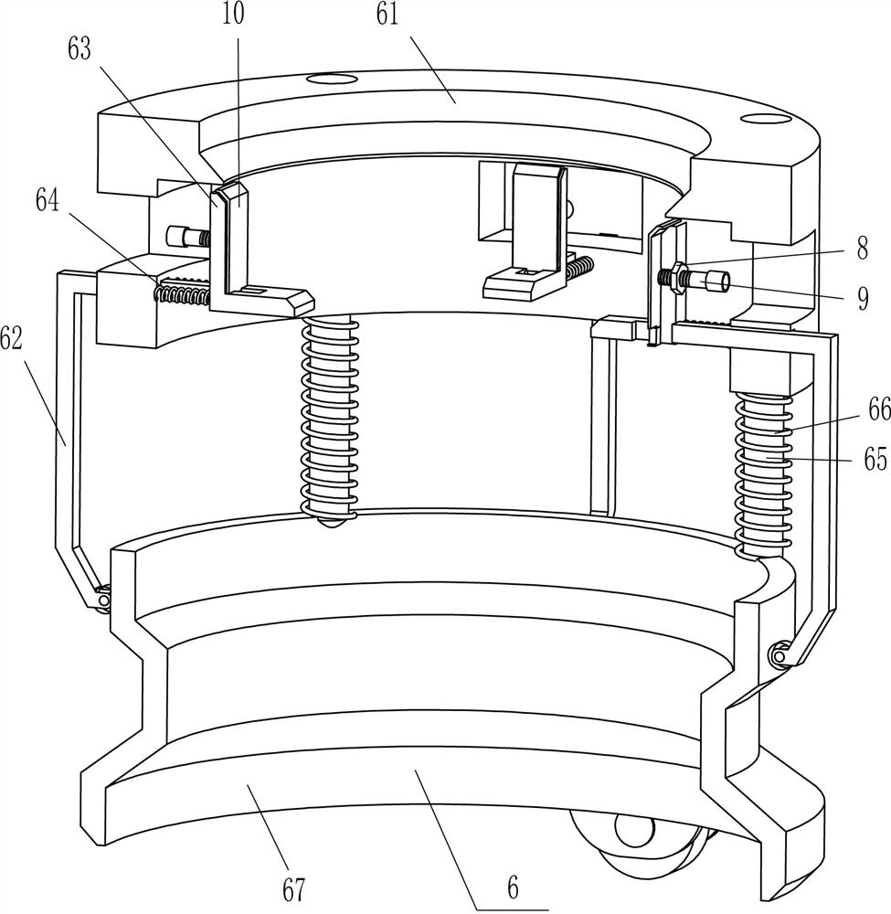
[0039] On the basis of embodiment 1 and embodiment 2, such as figure 2 , image 3 , Figure 4 and Figure 7 As shown, it also includes a nut 8, a screw rod 9 and a movable plate 10, the upper middle of the outer surface of the L-shaped placement plate 63 is fixedly connected with a nut 8, the screw rod 9 is threaded on the nut 8, and the inner end of the screw rod 9 runs through the L-shaped placement plate 63 The movable plate 10 is connected with the rotary type, and the bottom of the movable plate 10 is slidably matched with the inner bottom of the L-shaped placing plate 63 .

[0040] It also includes an L-shaped block 11, a clamping rod 12 and a sixth spring 14, six clamping holes 13 are evenly spaced around the lower part of the rotating rod 77, and an L-shaped block 11 is fixed symmetrically on the right side of the bottom of the mounting block 76. , the inner ends of the L-shaped blocks 11 on the front and rear sides are slidably placed with clamping rods 12, the inne...


PUM


Abstract

The invention relates to forming equipment, in particular to button surface heat treatment forming equipment. According to the button surface heat treatment forming equipment, buttons with pressed lines can be pushed out, people do not need to take down the buttons with hands, convenience is achieved, the working efficiency is high, people do not need to continuously place the buttons with hands,and labor is saved. The button surface heat treatment forming equipment comprises a base, wherein four L-shaped plates are fixedly connected to one side of the base at intervals. A button is placed among the four L-shaped containing plates, a telescopic rod of an air cylinder is started to be shortened, the L-shaped containing plates can drive the buttons to move to the position under a punching head, when an n-shaped sliding rod drives a special-shaped sliding plate to move leftwards, the punching head moves downwards to press out lines on the surface of the button, and then when the button moves to the right side, the L-shaped containing plates loosen the button, and the button falls into a collecting container, so that the button does not need to be taken down by hands of people, the operation is convenient, and the working efficiency is high.

Description

technical field [0001] The invention relates to a forming device, in particular to a button surface heat treatment forming device. Background technique [0002] With the rise of fast fashion, the button has changed from the previous functional type to the creative type. When the button is processed, in order to make the button more beautiful, the surface of the button will be embossed with lines. [0003] At present, most of the patterns are pressed out on the surface of the button by the cooperation of man and machine. First, people put the button into the machine, and then start the machine to press the pattern on the surface of the button. It is cumbersome to take it off, the work efficiency is low, and people need to constantly put the button into the machine by hand, which is laborious. [0004] Therefore, there is a special need for a button surface heat treatment molding equipment that can push out the pressed buttons without the need for people to take them off by h...

Claims


Application Information

Patent Timeline
IPC IPC(8): C21D9/00C21D1/00
CPCC21D9/0068C21D1/00B30B11/26
Inventor 李艾清
Owner 李艾清
Why Eureka
Try Eureka