
Plug-free door lock fixing structure

A fixed structure and door lock technology, applied in the field of door locks, can solve problems such as low efficiency, long reserved wires, and poor user experience

Active Publication Date: 2021-02-02
GUANGZHOU LANGO ELECTRONICS TECH CO LTD
View PDF12 Cites 0 Cited by
  • Summary
  • Abstract
  • Description
  • Claims
  • Application Information

AI Technical Summary

Problems solved by technology

[0005] However, due to the long reserved wires, after installing the wires, it is necessary to plug the wires into the door opening, or arrange the wires carefully so as not to press the wires after installing the second panel, which is inefficient and extremely user-friendly. Difference

Method used


Image

  • Plug-free door lock fixing structure
  • Plug-free door lock fixing structure
  • Plug-free door lock fixing structure

Examples


Embodiment Construction

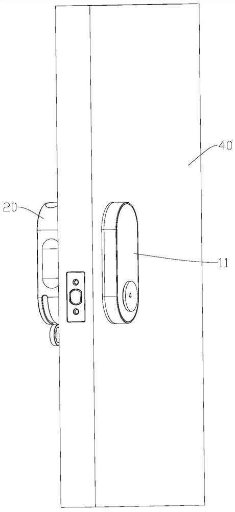
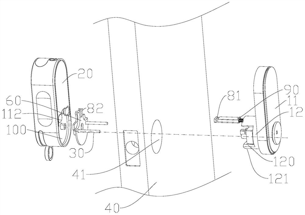
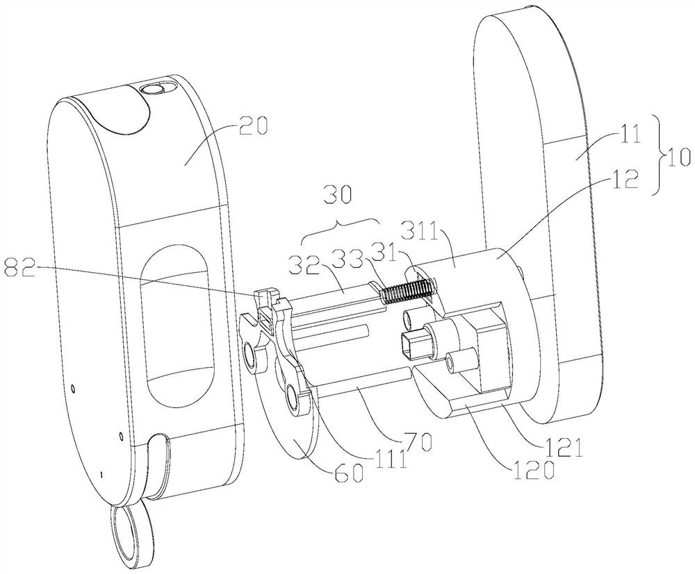
[0025] Such as Figure 1-3 As shown, a wire-free door lock structure includes a first panel 10, a second panel 20, a socket, a plug 50, a fixing plate 60 and a locking unit; the telescopic assembly 30 includes a first telescopic rod 31, a second telescopic Rod 32 and elastic element 33; The first telescopic rod 31 is installed on the first panel 10, specifically, the first telescopic rod 31 is installed on the face of the first panel 10 facing the door 40; the second telescopic rod 32 can be opposite to the first telescopic rod 31 is telescopically installed on the first telescopic rod 31, it can be understood that, when the second telescopic rod 32 stretches out relative to the first telescopic rod 31, it moves away from the first panel 10, and correspondingly, the second telescopic rod 32 relatively When the first telescopic rod 31 is retracted, it moves toward the direction close to the first panel 10; the elastic element 33 is used to provide the elastic stress that makes ...


PUM


Abstract

The invention discloses a plug-free door lock fixing structure. The plug-free door lock fixing structure comprises a first panel, a second panel, a telescopic assembly, a socket, a plug, a fixing plate and a locking unit. The telescopic assembly comprises a first telescopic rod, a second telescopic rod and an elastic element. The first telescopic rod is mounted on the first panel. The second telescopic rod is mounted on the first telescopic rod in the mode of being capable of stretching out and drawing back relative to the first telescopic rod. The elastic element is used for providing elasticstress for promoting the second telescopic rod to stretch out relative to the first telescopic rod. The socket is mounted on the second telescopic rod. The fixing plate can be detachably connected with the second telescopic rod. The locking unit is used for locking the fixing plate to the first panel. The plug is fixed to the second panel and can be matched with the socket. The plug-free door lock fixing structure can be suitable for doors of different thicknesses, wire arrangement is not needed, and therefore efficiency is improved, and the experience feeling is improved.

Description

technical field [0001] The invention relates to the field of door locks, in particular to a wire-free door lock fixing structure. Background technique [0002] Smart door locks usually consist of a first panel installed indoors and a second panel installed outdoors, where the power supply system is installed on the first panel, and the power supply for the second panel is provided by the first panel; now solve the problems of the first panel and the second panel. The electrical connection method of the two panels is: connect the wires on the first panel, and when installing the smart door lock, the user inserts the wires into the second panel; however, the existing wires usually need to be reserved for a long time due to the following reasons: [0003] 1. Due to the different thickness of the door, it is necessary to reserve a relatively long wire to adapt to different doors; [0004] 2. When inserting the wires, the first panel has been fixed on the door. In order to inser...

Claims


Application Information

Patent Timeline
IPC IPC(8): E05B9/08E05B15/00E05B17/00E05B47/00
CPCE05B9/08E05B15/00E05B17/00E05B47/00
Inventor 蔡逸群颜专
Owner GUANGZHOU LANGO ELECTRONICS TECH CO LTD
Learn More