Fan for air source heat pump

An air source heat pump and fan technology, applied to pumps, pump devices, pump components, etc., can solve problems such as trouble and difficulty for maintenance personnel, low mobility, etc., and achieve the effect of saving energy

Inactive Publication Date: 2021-02-02
湖南哲能赫新能源有限责任公司
View PDF11 Cites 0 Cited by
  • Summary
  • Abstract
  • Description
  • Claims
  • Application Information

AI Technical Summary

Problems solved by technology

[0004] The purpose of the present invention is to provide a fan for air source heat pump to solve the problem that the existing fan for air source heat pump proposed in the above background technology is not very maneuverable, whether it is for the user to overhaul it or replace the inside Parts, bring inevitable trouble and difficult problems to the overhauler

Method used


Image

  • Fan for air source heat pump
  • Fan for air source heat pump
  • Fan for air source heat pump

Examples


Embodiment Construction

[0026] The following will clearly and completely describe the technical solutions in the embodiments of the present invention with reference to the accompanying drawings in the embodiments of the present invention. Obviously, the described embodiments are only some, not all, embodiments of the present invention. Based on the embodiments of the present invention, all other embodiments obtained by persons of ordinary skill in the art without making creative efforts belong to the protection scope of the present invention.

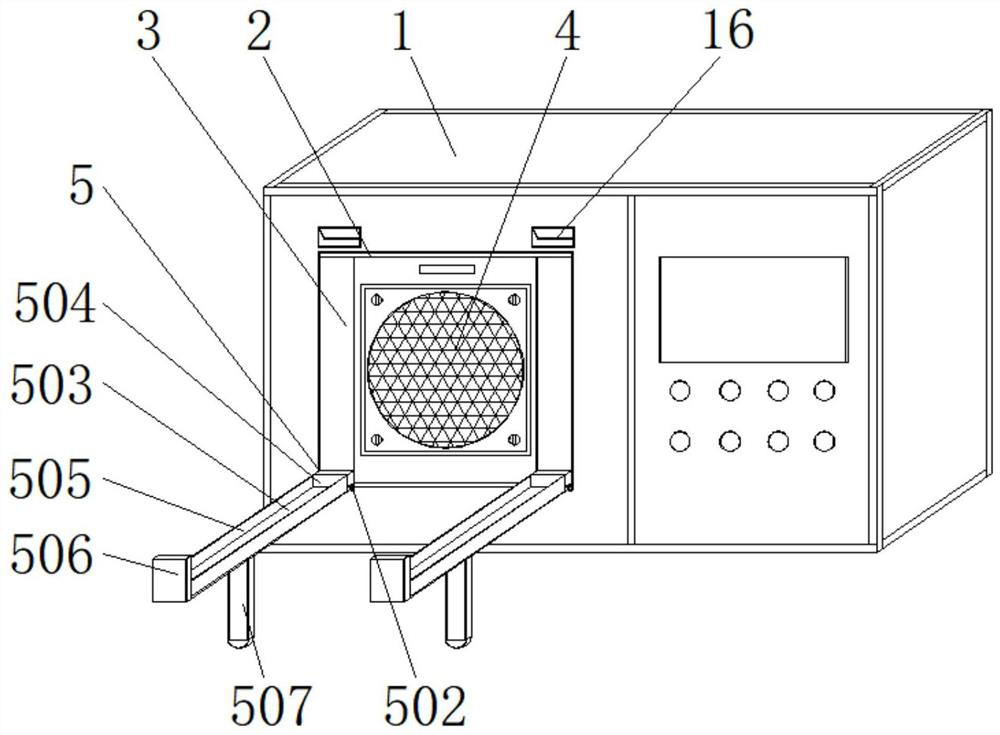
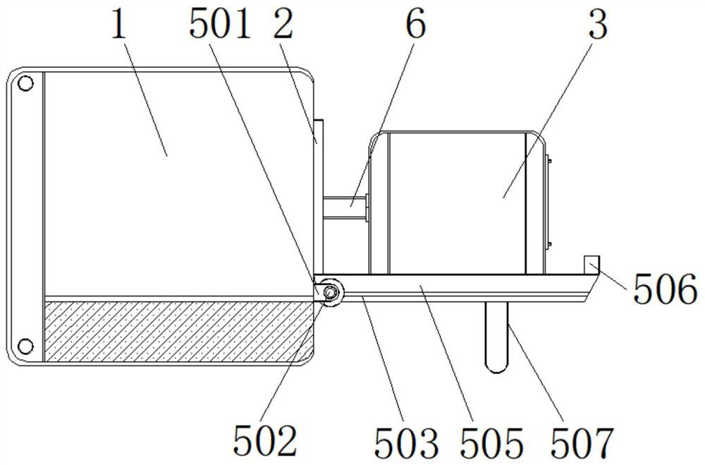
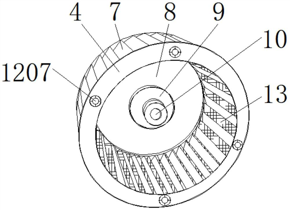
[0027] see Figure 1-5 , the present invention provides a technical solution: an air source heat pump fan, including a chassis 1, a fan outlet 2, a fan cabinet 3, a fan component 4, a sliding support mechanism 5, a welding rod 501, a rotating shaft 502, an orientation guide rail 503, Guide block 504, orientation plate 505, embedded block 506, support rod 507, hydraulic rod 6, outlet fan 7, motor rear cover 8, fixed block 9, embedded groove 10, hydraulic seat 1...


PUM


Abstract

The invention discloses a fan for an air source heat pump. The fan comprises a case and a fan part, wherein a fan port is formed in the front end of the case, a fan cabinet is installed on the inner wall of the fan port slidably, the fan part is embedded in the middle of the fan cabinet, a sliding supporting mechanism is installed below the fan part, and a hydraulic rod is connected to the middleof the rear end of the fan part. An air outlet fan is arranged on the outer wall of the periphery of the fan part, silencing cotton is attached to the outer wall of one side of the air outlet fan, a motor rear cover is installed at the position, close to the front end, of the middle of the fan part, a fixing block is connected to the rear end of the motor rear cover, an embedding groove is formedin the middle of the fixing block, a hydraulic base is connected to the rear end of the hydraulic rod, and a mounting plate is fixed on the outer wall of one side of the hydraulic base. The fan part is arranged, the fan part and the guide block form a sliding structure through the directional guide rail, and when a user needs to regularly overhaul and maintain the fan part, a daily case disassembling method is tedious, and inconvenience is brought to maintainers.

Description

technical field [0001] The invention relates to the field of air source heat pumps, in particular to a fan for air source heat pumps. Background technique [0002] The air source heat pump is an energy-saving device that uses high-level energy to make heat flow from low-level heat source air to high-level heat source. It is a form of heat pump. As the name implies, a heat pump is like a pump, which can convert low-level thermal energy that cannot be directly used (such as the heat contained in air, soil, and water) into high-level thermal energy that can be used, thereby saving some high-level energy (such as coal, gas, oil, etc.) , electricity, etc.) purpose. [0003] Existing fans for air source heat pumps are not very mobile, which brings unavoidable trouble and difficulty to the maintenance personnel no matter when the user is overhauling or replacing the internal parts. Contents of the invention [0004] The purpose of the present invention is to provide a fan for ...

Claims


Application Information

Patent Timeline
Patent Type & Authority Applications(China)
IPC IPC(8): F04D29/42F04D29/28F04D29/00F04D29/62F04D29/66F04D25/06
CPCF04D29/4226F04D29/281F04D29/002F04D29/626F04D29/664F04D29/666F04D25/0693
Inventor 雷凯
Owner 湖南哲能赫新能源有限责任公司
Why Eureka
Try Eureka