
Damping unit with torque limiter arranged between spring damper and centrifugal pendulum

A technology of torque limiter and spring shock absorber, applied in the direction of spring/shock absorber, rotational vibration suppression, vibration suppression adjustment, etc., can solve the problem of large design size of vibration damping unit, and achieve the effect of solid design

Pending Publication Date: 2021-02-02
SCHAEFFLER TECH AG & CO KG
View PDF2 Cites 0 Cited by
  • Summary
  • Abstract
  • Description
  • Claims
  • Application Information

AI Technical Summary

Problems solved by technology

[0003] However, in the embodiments known from the prior art, the disadvantage is found that the damping units implemented are usually realized with relatively large design dimensions

Method used


Image

  • Damping unit with torque limiter arranged between spring damper and centrifugal pendulum
  • Damping unit with torque limiter arranged between spring damper and centrifugal pendulum
  • Damping unit with torque limiter arranged between spring damper and centrifugal pendulum

Examples


Embodiment Construction

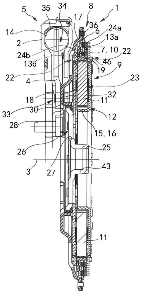
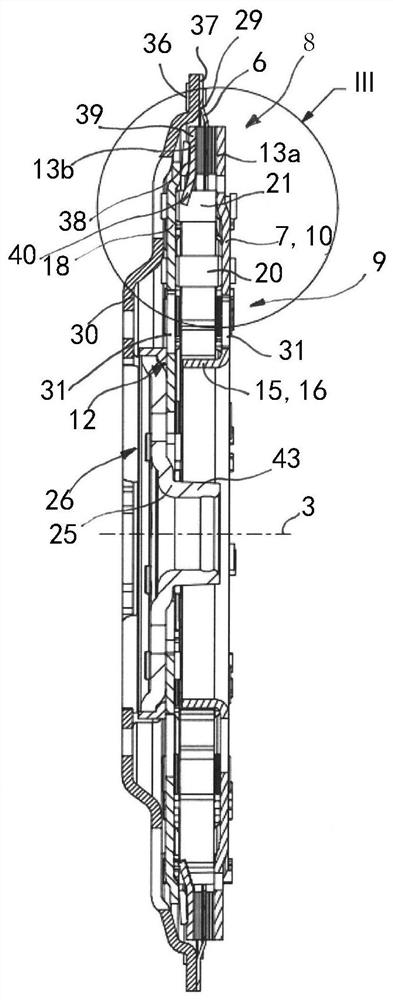
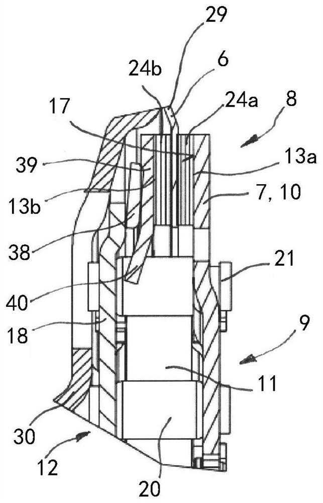
[0037] with the help of figure 1 The vibration-damping unit 1 according to the invention which corresponds to the preferred embodiment in its construction is clearly shown. The damping unit 1 is designed for a hybrid motor vehicle drivetrain. The damping unit 1 is therefore used for damping torsional vibrations that occur during operation of the motor vehicle drivetrain. Viewed along the torque transmission path, the damping unit 1 is usually installed between the crankshaft of the internal combustion engine and the transmission of the powertrain. The damping unit 1 basically has three components. A first component is realized in the form of a spring damper 5 , a second component is realized in the form of a torque limiter 8 and a third component is realized in the form of a centrifugal pendulum 9 . These three components 5, 8, 9 are arranged in series / tandem along the torque transmission path.

[0038] Regarding the spring damper 5, in figure 1 It can also be seen in FIG...


PUM


Abstract

The invention relates to a damping unit suitable for a motor vehicle drive train, comprising a spring damper having a primary part and a secondary part which is elastically supported in the directionof rotation about a central axis of rotation relative to the primary part; the torque limiter is provided with two fixed friction pairs which are connected with each other in an anti-torsion manner when working in a specific torque threshold range; wherein the torque limiter and the centrifugal pendulum are operatively connected to the secondary part, a first friction pair of the torque limiter isconnected to the secondary part and a second friction pair of the torque limiter is connected to a side plate of a housing of the centrifugal pendulum that accommodates a plurality of pendulum masses, and the pendulum bob mass is radially positioned in a contact part formed between the friction pairs and is at least partially positioned at the same height as the axial direction of the first friction pair.

Description

technical field [0001] The invention relates to a vibration damping unit suitable for use in (preferably hybrid drive) motor vehicle powertrains, such as cars, trucks, buses or other commercial vehicle powertrains, said damping unit having: a spring A shock absorber with a primary part and a secondary part resiliently supported relative to said primary part in the direction of rotation about a central axis of rotation; a torque limiter with two fixed, operating within a specific torque threshold friction pairs connected to each other in a torsionally fixed manner; and a centrifugal pendulum, wherein the torque limiter and the centrifugal pendulum are operatively connected to the secondary part. Background technique [0002] Such background art is well known. Correspondingly, EP 2 685 127 B1 discloses, for example, a vibration damping device with an elastic damping mechanism, a torque limiting mechanism and a pivoting vibration damping mechanism. Further background art is k...

Claims


Application Information

Patent Timeline
IPC IPC(8): F16F15/14
CPCF16F15/145F16F15/1407F16F15/1397
Inventor A·鲁施P·克伦佩尔J·劳E·弗朗茨
Owner SCHAEFFLER TECH AG & CO KG
Learn More