
Optical fiber ring implementation method of a small-caliber cylindrical high-precision optical fiber gyroscope

A technology of fiber optic gyroscope and implementation method, which is applied in Sagnac effect gyroscopes, gyroscope/steering sensing equipment, measuring devices, etc., to achieve the effect of improving output accuracy and realizing high-precision performance

Inactive Publication Date: 2021-02-02
XIAN SINO HUAXIN MEASUREMENT & CONTROL
View PDF5 Cites 0 Cited by
  • Summary
  • Abstract
  • Description
  • Claims
  • Application Information

AI Technical Summary

Problems solved by technology

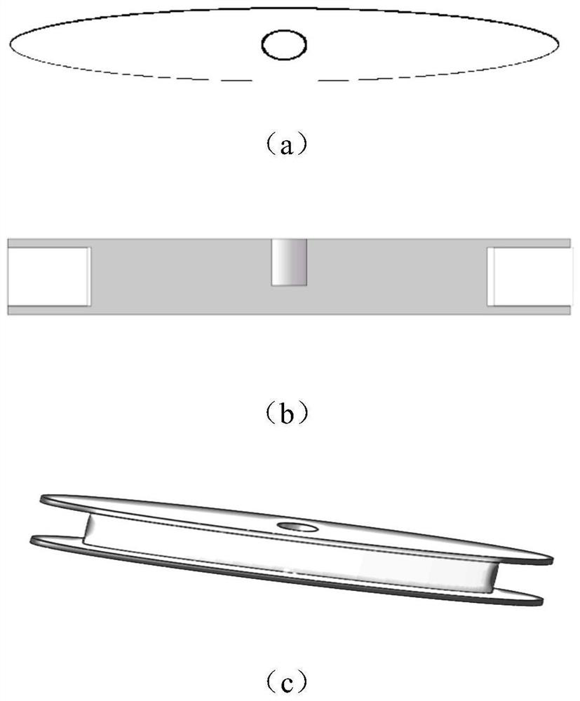
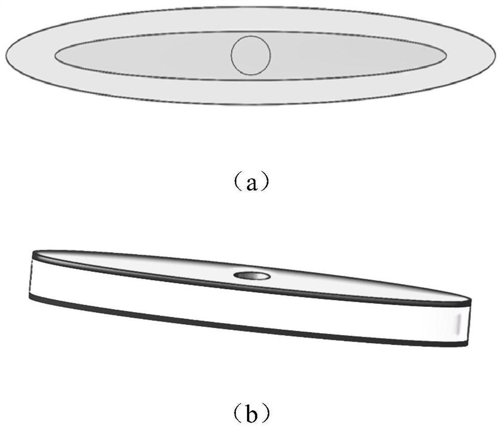
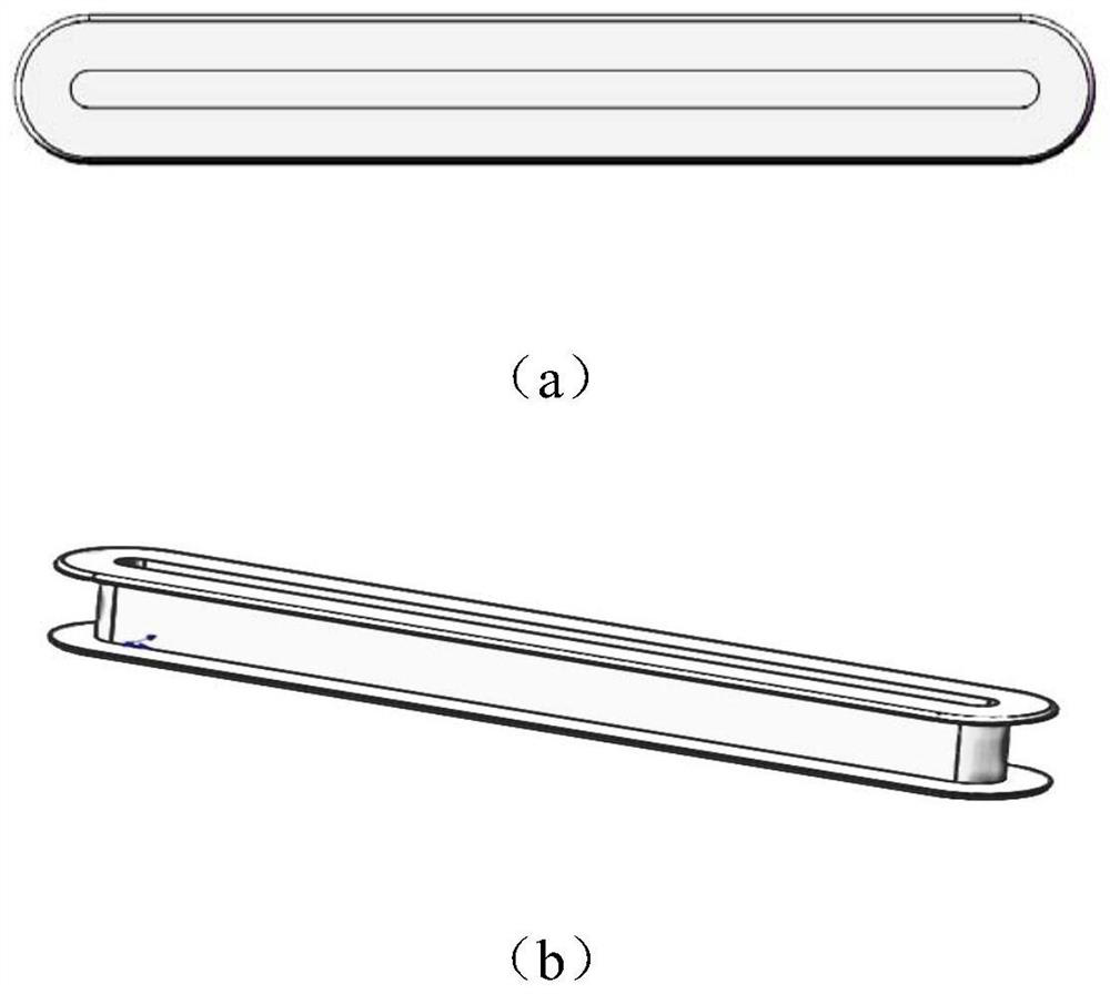
[0003] The object of the present invention is to provide a method for realizing a fiber optic loop of a small-diameter cylindrical high-precision fiber optic gyroscope, to solve the contradiction between the limited diameter of the fiber optic loop and the longer winding length of the fiber (to achieve high precision) required by special environments, The present invention uses several circular symmetric optical fiber rings with winding rules to offset the asymmetrical stress generated during the winding process between multiple optical fiber rings, and greatly enhances the temperature gradient of the optical fiber rings when the aperture is limited. Adaptability, thus greatly improving the output accuracy of fiber optic gyroscopes, and laying a solid foundation for applications in special fields (such as oil well inclinometers)

Method used


Image

  • Optical fiber ring implementation method of a small-caliber cylindrical high-precision optical fiber gyroscope
  • Optical fiber ring implementation method of a small-caliber cylindrical high-precision optical fiber gyroscope
  • Optical fiber ring implementation method of a small-caliber cylindrical high-precision optical fiber gyroscope

Examples


Embodiment Construction

[0025] In order to clearly illustrate the present invention, the present invention will be further described in detail below in conjunction with the embodiments and accompanying drawings. Those skilled in the art understand that the following content does not limit the protection scope of the present invention, and any improvements and changes made on the basis of the present invention are within the protection scope of the present invention.

[0026] The invention adopts the design of a plurality of small cylindrical optical fiber rings to ensure the winding length of the optical fiber under the condition of limited diameter. In order to improve the heterogeneity of the connection methods of multiple cylindrical fiber rings, and to offset the asymmetric stress generated in the winding process between multiple fiber rings, two connection methods between cylindrical fiber rings were designed, and a targeted proposal was made. Technical requirements for optical fiber surround sy...


PUM

PropertyMeasurementUnit
Diameter sizeaaaaaaaaaa
Sizeaaaaaaaaaa
Diameter sizeaaaaaaaaaa

Abstract

The invention discloses an optical fiber ring implementation method of a small-caliber cylindrical high-precision optical fiber gyroscope, which adopts a mode that a plurality of small cylindrical optical fiber rings are connected in parallel, the lengths of optical fibers wound by each cylindrical optical fiber ring are the same, the winding tensions are the same, and a plurality of cylindrical optical fiber rings are wound from one end; or the first cylindrical optical fiber ring is wound from the midpoint of the total optical fiber length, and the subsequent cylindrical optical fiber ring is wound from the tail fiber of the previous cylindrical optical fiber ring. According to the invention, asymmetric stress generated in the winding process of the plurality of optical fiber rings is correspondingly offset through the plurality of optical fiber rings with circular symmetrical structures and winding rules, and the adaptive capacity of the optical fiber rings to the temperature gradient is greatly enhanced under the condition that the caliber is limited, so that the output precision of the optical fiber gyroscope is greatly improved; and a solid foundation is laid for applicationin special fields (such as oil well inclinometry).

Description

technical field [0001] The invention relates to the field of small-diameter cylindrical high-precision optical fiber gyroscopes, in particular to a method for realizing an optical fiber ring of small-diameter cylindrical high-precision optical fiber gyroscopes. Background technique [0002] Small-diameter cylindrical high-precision fiber optic gyroscopes are mainly used in some special fields, such as the field of oil well inclinometer. These special environments put forward requirements for fiber optic gyroscopes with small diameter (small aperture), high precision and wide operating temperature range. Among these requirements, the requirement of small diameter leads to the limitation of the diameter of the sensing fiber ring of the fiber optic gyroscope, and it is difficult to wind a fiber ring with a long fiber length; but the requirement of high precision also requires a fiber ring with a long fiber winding length. These two requirements restrict each other to a certain...

Claims


Application Information

Patent Timeline
IPC IPC(8): G01C19/72
CPCG01C19/721
Inventor 王辉张斌辛治奇
Owner XIAN SINO HUAXIN MEASUREMENT & CONTROL
Learn More