Backlight module and display device

A backlight module and display device technology, which is applied in the direction of identification devices and instruments, can solve the problems of separation of the reflective layer, small adhesion between the reflective layer and the drive circuit layer, etc., to increase the adhesion, reduce the small risk effect

Active Publication Date: 2021-02-02
WUHAN CHINA STAR OPTOELECTRONICS TECH CO LTD
View PDF10 Cites 6 Cited by
  • Summary
  • Abstract
  • Description
  • Claims
  • Application Information

AI Technical Summary

Problems solved by technology

[0005] The embodiment of the present application provides a backlight module and a display device, which are used to solve the problem of separation of the reflective layer due to the weak adhesion between the reflective layer and the surface of the driving circuit layer in the existing mini light-emitting diode backlight module

Method used


Image

  • Backlight module and display device
  • Backlight module and display device
  • Backlight module and display device

Examples


Embodiment Construction

[0029] The following descriptions of the various embodiments refer to the accompanying drawings to illustrate specific embodiments that the present application can be used to implement. The directional terms mentioned in this application, such as [top], [bottom], [front], [back], [left], [right], [inside], [outside], [side], etc., are for reference only The orientation of the attached schema. Therefore, the directional terms used are used to illustrate and understand the application, but not to limit the application. In the figures, structurally similar elements are denoted by the same reference numerals.

[0030] The present application will be further described below in conjunction with the accompanying drawings and specific embodiments.

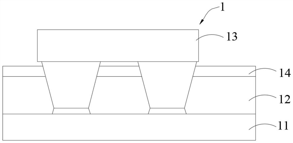
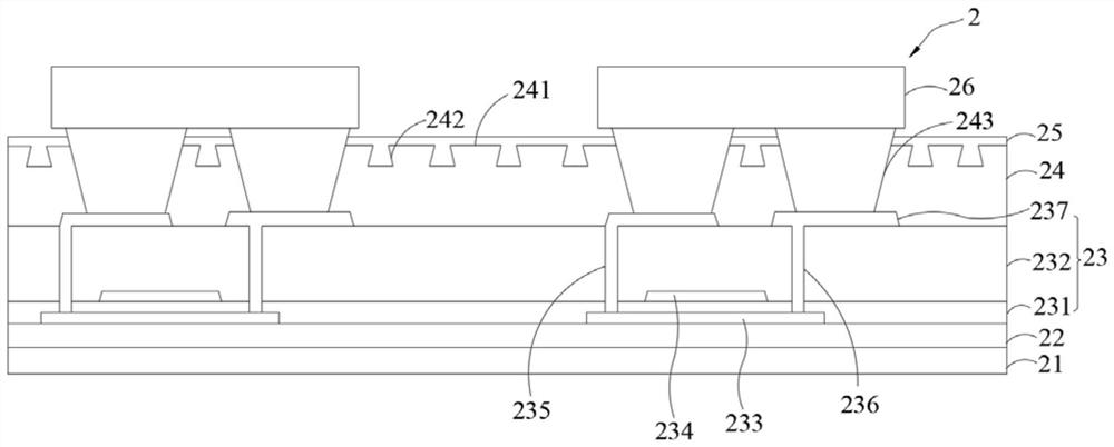
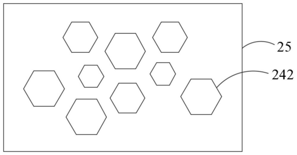
[0031] The embodiment of the present application provides a backlight module, which is combined with figure 2 Describe in detail. Such as figure 2 as shown, figure 2 The cross-sectional schematic diagram of the backlight module pr...


PUM

PropertyMeasurementUnit
widthaaaaaaaaaa
thicknessaaaaaaaaaa
widthaaaaaaaaaa

Abstract

The invention provides a backlight module and a display device. The backlight module comprises a substrate, a drive circuit layer arranged on the substrate, a protective layer arranged on the side, away from the substrate, of the drive circuit layer, a light reflecting layer arranged on the side, away from the drive circuit layer, of the protective layer, and a plurality of light emitting diode chips arranged on the side, away from the protective layer, of the light reflecting layer in an array mode. An uneven surface is arranged on the side, close to the reflective layer, of the protective layer, the adhesive force between the surface of the side, close to the reflective layer, of the protective layer and the reflective layer is increased, so that the risk of film separation of the reflective layer is reduced.

Description

technical field [0001] The invention relates to the field of display technology, in particular to a backlight module and a display device. Background technique [0002] Mini LED BLU (mini light emitting diode back light unit, Mini LED BLU) has gradually become the mainstream backlight technology due to its high brightness and local dimming function. By designing thin-film transistors to drive light-emitting diode chips on the driving circuit layer of the mini light-emitting diode backlight module, using thin-film transistors to realize active driving can greatly reduce the number of driving integrated circuit chips, and achieve more partition adjustments, thus giving the display The device brings better display effect. [0003] Such as figure 1 as shown, figure 1 It is a structural schematic diagram of a mini LED backlight module in the prior art. The mini LED backlight module 1 is composed of a base substrate 11, a driving circuit layer 12 and a LED chip 13, and usually ...

Claims


Application Information

Patent Timeline
Patent Type & Authority Applications(China)
IPC IPC(8): G09F9/00
CPCG09F9/00
Inventor 刘凡成查国伟
Owner WUHAN CHINA STAR OPTOELECTRONICS TECH CO LTD
Why Eureka
Try Eureka