Automatic lifting type power distribution cabinet capable of preventing water logging

A technology for automatic lifting and distribution cabinets, which is applied to the substation/distribution device casing, electrical components, substation/switch layout details, etc., and can solve problems such as floods, unsatisfactory waterproof performance of distribution cabinets, time-consuming and labor-intensive problems

Inactive Publication Date: 2021-02-02
广州诺言科技有限公司
View PDF0 Cites 1 Cited by
  • Summary
  • Abstract
  • Description
  • Claims
  • Application Information

AI Technical Summary

Problems solved by technology

[0003] Some power distribution cabinets are installed in low-lying places. In rainy weather, there will be water on the ground or even floods. Since the power distribution cabinets are generally equipped with cooling holes, the accumulated water will flow into the inside of the distribution cabinet from the cooling holes, which may It will cause damage to electrical equipment and cause circuit failure. The existing power distribution cabinets are generally lifted manually to prevent the power distribution cabinet from being soaked, but this consumes a lot of time and manpower, and if the operation is not timely, it will not be able to achieve waterproofing. purpose, so the anti-flooding effect is not ideal
[0004] Aiming at the deficiencies of the prior art, the present invention provides an automatic lifting power distribution cabinet that can prevent flooding, which has the advantages of automatic lifting power distribution cabinet, energy saving and environmental protection, and improved waterproofness of equipment, and solves the problem of waterproofing of general power distribution cabinets. The problem of suboptimal performance

Method used


Image

  • Automatic lifting type power distribution cabinet capable of preventing water logging
  • Automatic lifting type power distribution cabinet capable of preventing water logging
  • Automatic lifting type power distribution cabinet capable of preventing water logging

Examples


Embodiment Construction

[0025] The following will clearly and completely describe the technical solutions in the embodiments of the present invention with reference to the accompanying drawings in the embodiments of the present invention. Obviously, the described embodiments are only some, not all, embodiments of the present invention. Based on the embodiments of the present invention, all other embodiments obtained by persons of ordinary skill in the art without making creative efforts belong to the protection scope of the present invention.

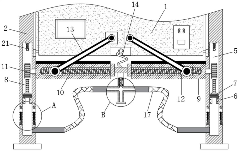
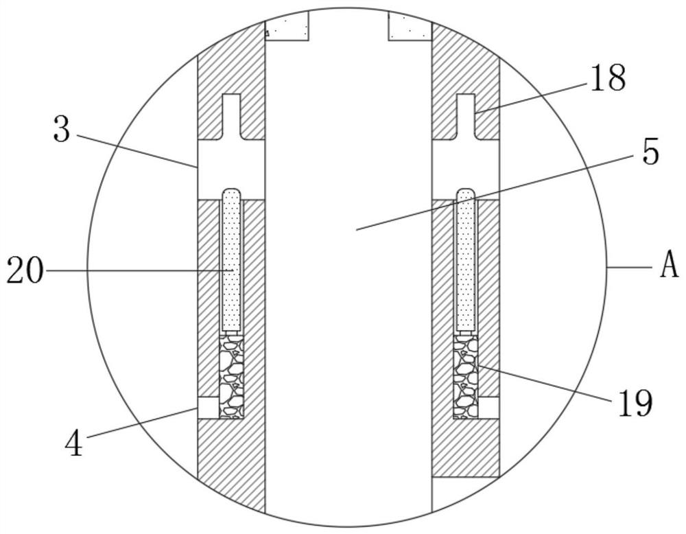
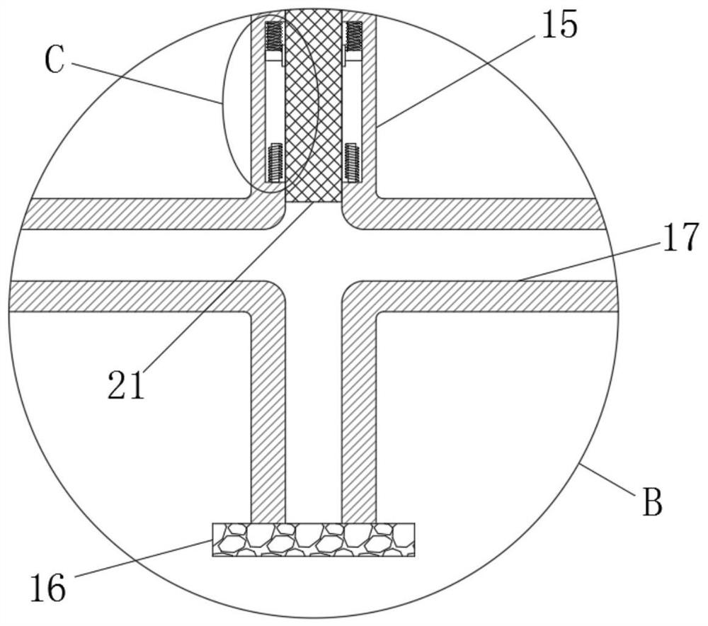
[0026] see Figure 1-4 , an automatic lifting power distribution cabinet that can prevent flooding, including a cabinet body 1, a pillar 2 is slidably connected to both sides of the cabinet body 1, and the lower side of the pillar 2 is provided with an exhaust hole 3 and The upper end of the through hole 4 and the exhaust hole 3 is provided with a card slot 18, and the side of the through hole 4 close to the cavity 5 is provided with a water-absorbing swellabl...


PUM


Abstract

The invention relates to the technical field of power distribution cabinets, and discloses an automatic lifting type power distribution cabinet capable of preventing flooding, which comprises a cabinet body, both sides of the cabinet body are slidably connected with support columns, both sides of the lower column body of each support column are provided with exhaust holes and through holes, and the inner part of each support column is provided with a cavity; and limiting blocks are fixedly connected to the inner walls of the two sides of the cavity. According to the automatic lifting type power distribution cabinet capable of preventing water logging, the water-absorbing expansion rubber absorbs water to expand and pushes the baffle to move upwards to be inserted into the clamping groove,the exhaust hole is blocked by the baffle at the moment, hot air cannot be exhausted, the pressure intensity in the cavity below the piston is increased, the piston is pushed upwards accordingly, andthe gear is driven to rotate through the rack; the screw synchronously rotates along with the support column and drives the threaded block to move away from the support column, and the threaded blockdrives the cabinet body to move upwards through the guide rod, thereby achieving the rising of the power distribution cabinet, and preventing accumulated water from entering the power distribution cabinet.

Description

technical field [0001] The invention relates to the technical field of power distribution cabinets, in particular to an automatic lifting type power distribution cabinet that can prevent flooding. Background technique [0002] The power distribution cabinet is also called the distribution box, which is divided into power distribution cabinet, lighting distribution cabinet and metering cabinet. Power distribution cabinets are generally used in places where the load is relatively scattered and the circuit is small, such as the substation of an enterprise. [0003] Some power distribution cabinets are installed in low-lying places. In rainy weather, there will be water on the ground or even floods. Since the power distribution cabinets are generally equipped with cooling holes, the accumulated water will flow into the inside of the distribution cabinet from the cooling holes, which may It will cause damage to electrical equipment and cause circuit failure. The existing power d...

Claims


Application Information

Patent Timeline
Patent Type & Authority Applications(China)
IPC IPC(8): H02B1/56H02B1/30H02B1/28
CPCH02B1/28H02B1/303H02B1/565
Inventor 杨启林
Owner 广州诺言科技有限公司
Why Eureka
Try Eureka