Unlock instant, AI-driven research and patent intelligence for your innovation.
Fireproof and smash-proof mobile intelligent bullet cabinet
What is Al technical title?
Al technical title is built by PatSnap Al team. It summarizes the technical point description of the patent document.
A mobile bullet cabinet technology, applied in the field of bullet cabinets, can solve the problems of no fixed protection device for guns, easy slipping of guns, inconvenient movement, etc., and achieve the effect of increasing the scope of application, easy placement and access, and simple structure
Inactive Publication Date: 2021-02-05
SHANGHAI GUANYIJIE IND CO LTD
View PDF5 Cites 3 Cited by
Summary
Abstract
Description
Claims
Application Information
AI Technical Summary
This helps you quickly interpret patents by identifying the three key elements:
Problems solved by technology
Method used
Benefits of technology
Problems solved by technology
[0003] However, some existing fireproof and anti-smashing smart bullet cabinets still have some shortcomings. First of all, most of the existing fireproof and anti-smashing intelligent bullet cabinets are not convenient to move or the bullet cabinets are directly supported by rollers, which may easily cause damage to the rollers. Secondly, most of the existing fireproof and anti-smashing intelligent bullet cabinets do not have fixed protection devices for guns. Hangers are used for fixing, but the commonly used hangers are fixed in structure, the scope of application is small, and the practicability is not high
Method used
Image
Click on the blue label to locate the original text in one second.
Reading with bidirectional positioning of images and text.
Examples
Embodiment 1
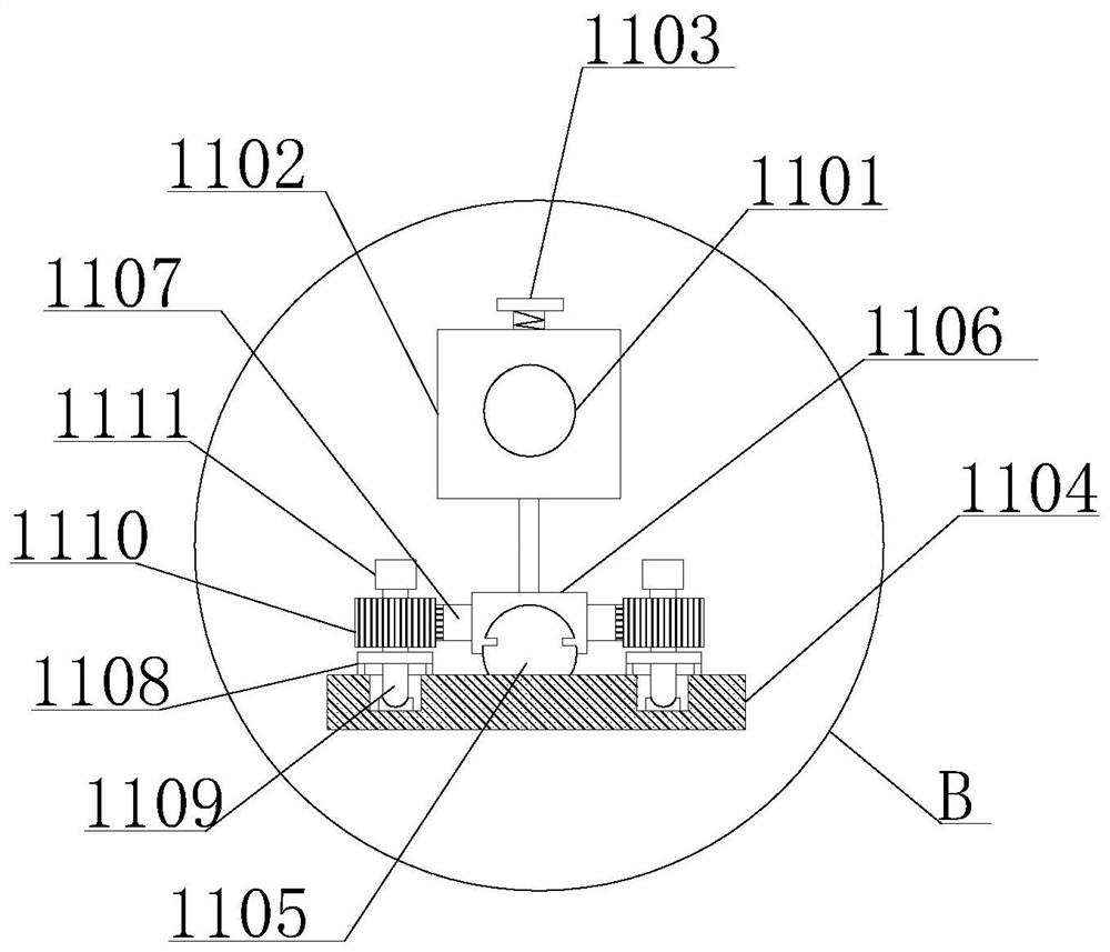
[0032] Embodiment 1, the bottom of the adjustment block 1102 is fixedly installed with a connecting rod. By moving the adjustment block 1102, the slider 1106 can be driven to slide on the surface of the slide rail 1105, and the gear and the rotating rod 1109 can be driven to rotate through the rack 1107, thereby adjusting the clamping arm 1111 dimensions.
Embodiment 2
[0033] In Embodiment 2, a locking knob is provided inside the adjusting block 1102 . When the adjusting block 1102 is moved to a suitable position, the locking knob 1103 is tightened to fix it, so that the clamping arm 1111 can firmly clamp the firearm.
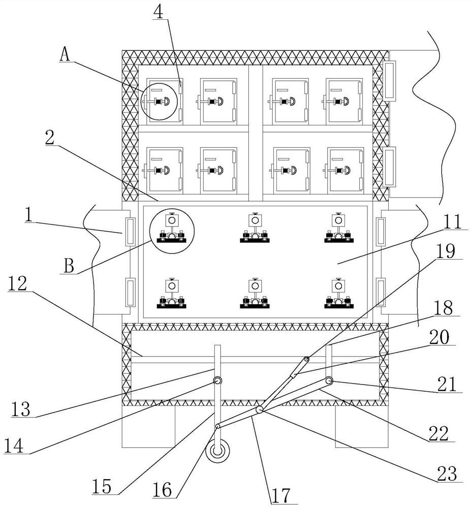
[0034] Working principle: When the cylinder 20 is stretched out, it drives the third connecting rod 22 to rotate counterclockwise outside the fourth rotating shaft 21, the cylinder 20 rotates counterclockwise outside the third rotating shaft 19, and the first connecting rod 15 rotates clockwise outside the first rotating shaft 14 , the second connecting rod 17 rotates clockwise outside the fifth rotating shaft 23. At this time, the roller is released to facilitate movement. When the cylinder 20 is withdrawn, it drives the third connecting rod 22 to rotate clockwise outside the fourth rotating shaft 21. The outside of the rotating shaft 19 rotates clockwise, the first connecting rod 15 rotates counterclockwise outside the first...
PUM
Abstract
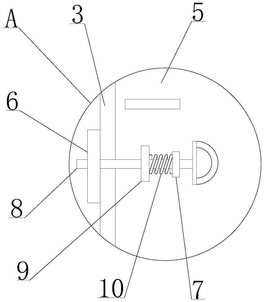
The invention discloses a fireproof and smash-proof mobile intelligent bullet cabinet. The cabinet comprises a cabinet body, a placing plate, a fixing box, first hinges, a box door, a first fixing plate, a second fixing plate, an inserting rod, a limiting plate, springs, a firearm placing cabinet, a third fixing plate, a first fixing rod, a first rotating shaft, a first connecting rod, a second rotating shaft, a second connecting rod, a second fixing rod, a third rotating shaft, an air cylinder, a fourth rotating shaft, a third connecting rod and a fifth rotating shaft. And the placing plate is fixedly mounted on the left side in the cabinet body, and the fixing box is fixedly mounted at the top of the placing plate. The bullet cabinet is provided with the air cylinder and the rolling wheels, so that the bullet cabinet is convenient to move; after the bullet cabinet moves to a designated position, the air cylinder can drive the rolling wheels to be retracted into the cabinet body, andthe cabinet body is supported through the supporting columns, so that the rolling wheels are prevented from being damaged due to load; by arranging the fixing box and the inserting rod, a gun can be placed in the fixing box, and the fixing box is sealed by the inserting rod; and gun damage caused by gun slipping when the cabinet body moves is avoided.
Description
technical field [0001] The invention relates to the technical field of bullet cabinets, in particular to a fireproof and smash-resistant mobile intelligent bullet cabinet. Background technique [0002] Guns and ammunition are special and dangerous items that can kill people. Improper management and use will seriously endanger public safety and affect people's normal life order. The so-called private possession refers to the act of hiding guns and ammunition in the premises without the qualifications for distributing and using guns according to the state's regulations on the management of guns and ammunition. In the jurisdiction, by hanging banners, distributing leaflets and security checks, etc., widely publicize the harm of privately stored guns, ammunition and explosives to society and individuals. Therefore, gun management personnel need highly secure gun cabinets to store guns. Therefore, there is a fireproof and anti-smashing intelligent bullet cabinet. [0003] Howev...
Claims
Application Information
Patent Timeline
Application Date:The date an application was filed.
Publication Date:The date a patent or application was officially published.
First Publication Date:The earliest publication date of a patent with the same application number.
Issue Date:Publication date of the patent grant document.
PCT Entry Date:The Entry date of PCT National Phase.
Estimated Expiry Date:The statutory expiry date of a patent right according to the Patent Law, and it is the longest term of protection that the patent right can achieve without the termination of the patent right due to other reasons(Term extension factor has been taken into account ).
Invalid Date:Actual expiry date is based on effective date or publication date of legal transaction data of invalid patent.
