Parts cleaning device for mechanical processing

A cleaning device and machining technology, applied in the field of parts processing, can solve the problems of waste of water resources, easy adhesion of oil stains, impurities, iron filings and other debris, difficult to clean mechanical parts, etc. The effect of fluency

Active Publication Date: 2021-09-21
EASTERN GANSU UNIVERSITY
View PDF6 Cites 0 Cited by
  • Summary
  • Abstract
  • Description
  • Claims
  • Application Information

AI Technical Summary

Problems solved by technology

[0003] At present, there are certain shortcomings in the processing and production of mechanical parts. During the processing, the surface of mechanical parts is easy to adhere to oil, impurities, iron filings and other sundries. The parts need to be cleaned. The usual cleaning method is to directly wash the machine with cleaning water Parts are washed, but this cleaning method is difficult to clean the bottom of mechanical parts, and it is a waste of water resources. Therefore, it is urgent to design a parts cleaning device for mechanical processing to solve the above problems

Method used


Image

  • Parts cleaning device for mechanical processing
  • Parts cleaning device for mechanical processing
  • Parts cleaning device for mechanical processing

Examples


Embodiment 1

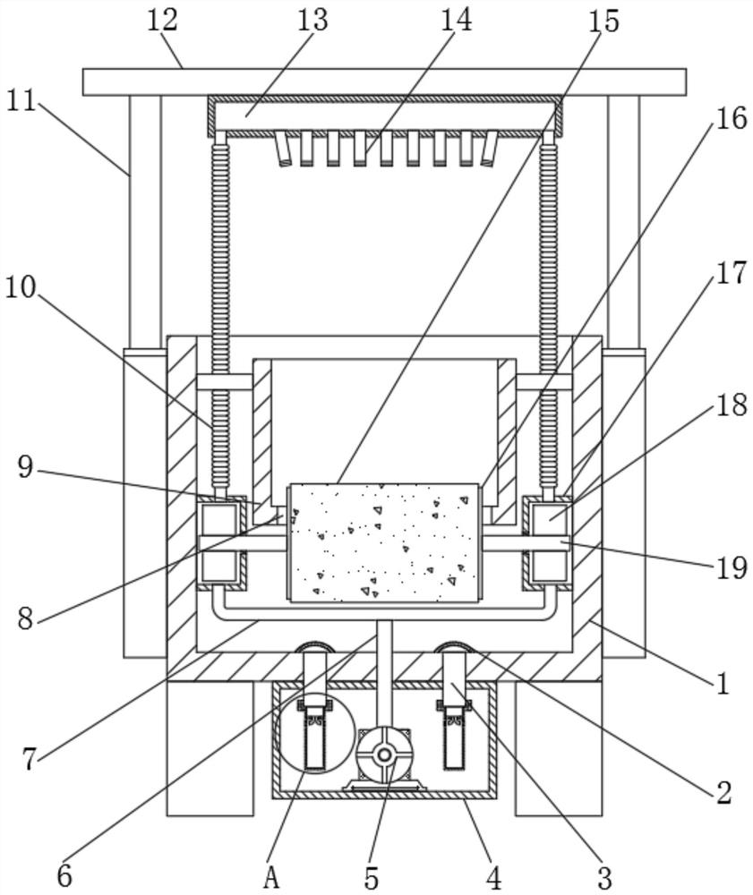
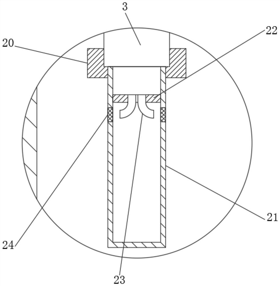
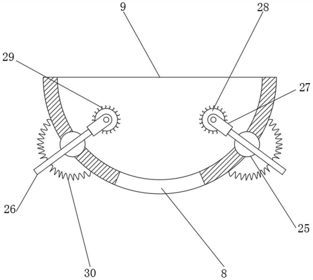
[0031] refer to Figure 1-4 , a parts cleaning device for mechanical processing, comprising a cleaning box 1, the inside of the cleaning box 1 is fixedly connected with a placement box 9 through a connecting rod, and the outer walls of the cleaning box 1 are fixedly connected with a hydraulic cylinder 11, and the hydraulic cylinder 11 One end of the piston is provided with a top plate 12, the bottom outer wall of the top plate 12 is provided with a square box 13, and the bottom outer wall of the square box 13 is provided with a plurality of nozzles 14, and the inner walls of both sides of the cleaning box 1 are fixedly connected with a fixed cover 17, and fixed The cover 17 and the square box 13 are connected by the bellows 10, the bottom outer wall of the cleaning tank 1 is fixedly connected with the liquid storage tank 4, and the inside of the liquid storage tank 4 is provided with a liquid pump 5, and the infusion end of the liquid pump 5 is provided with an infusion tube 6...

Embodiment 2

[0041] refer to Figure 5 , a parts cleaning device for mechanical processing. Compared with Embodiment 1, this embodiment also includes that four corners of the outer wall of the bottom of the square box 13 are provided with lighting lamps 32 .

[0042] Working principle: when in use, it is convenient to observe the cleaning status of the mechanical parts through the lighting lamp 32 at the bottom of the square box 13, and the use effect is better.


PUM


Abstract

The invention discloses a part cleaning device for mechanical processing, which comprises a cleaning box, the interior of the cleaning box is fixedly connected with a placement box through a connecting rod, and hydraulic cylinders are fixedly connected to the outer walls of the four sides of the cleaning box, and the hydraulic pressure One end of the piston of the cylinder is provided with a top plate, the bottom outer wall of the top plate is provided with a square box, and the bottom outer wall of the square box is provided with a plurality of nozzles, the inner walls of both sides of the cleaning box are fixedly connected with fixed covers, and the fixed covers and The square boxes are connected by bellows, the bottom outer wall of the cleaning tank is fixedly connected with a liquid storage tank, and a liquid pump is arranged inside the liquid storage tank, and an infusion tube is provided at the infusion end of the liquid pump, and the infusion tube One end is fixedly connected with a U-shaped pipe. The invention enables the cleaning liquid to be continuously recycled, meets the requirements of energy saving and environmental protection, and effectively ensures the smoothness of the cleaning water flow, so that the water pressure of the cleaning water sprayed out by the nozzle is always kept normal, and the use effect is better.

Description

technical field [0001] The invention relates to the technical field of part processing, in particular to a part cleaning device for mechanical processing. Background technique [0002] Mechanical parts, also known as mechanical components, are the basic components of machinery. They are inseparable individual parts that make up machinery and machines. General term. [0003] At present, there are certain shortcomings in the processing and production of mechanical parts. During the processing, the surface of mechanical parts is easy to adhere to oil, impurities, iron filings and other sundries. The parts need to be cleaned. The usual cleaning method is to directly wash the machine with cleaning water. Parts are washed, but this cleaning method is difficult to clean the bottom of mechanical parts, and it is a waste of water resources. Therefore, it is urgent to design a parts cleaning device for machining to solve the above problems. Contents of the invention [0004] The p...

Claims


Application Information

Patent Timeline
Patent Type & Authority Patents(China)
IPC IPC(8): B08B1/00B08B3/02B08B3/10B08B3/14B08B13/00
CPCB08B1/002B08B3/022B08B3/10B08B3/14B08B13/00
Inventor 边建潇郭晋昌连潇张建锐敬谦敬志臣
Owner EASTERN GANSU UNIVERSITY
Why Eureka
Try Eureka