
Electrical perforating device for electrical construction and using method

A punching device and electrical construction technology, applied in positioning devices, manufacturing tools, boring/drilling, etc., can solve problems such as inaccurate punching positions, unstable fixation, deformation of metal fittings, etc., to improve Convenience, improved safety and accuracy, the effect of a reasonable structure

Inactive Publication Date: 2021-02-05
国网山东省电力公司昌邑市供电公司 +1
View PDF10 Cites 4 Cited by
  • Summary
  • Abstract
  • Description
  • Claims
  • Application Information

AI Technical Summary

Problems solved by technology

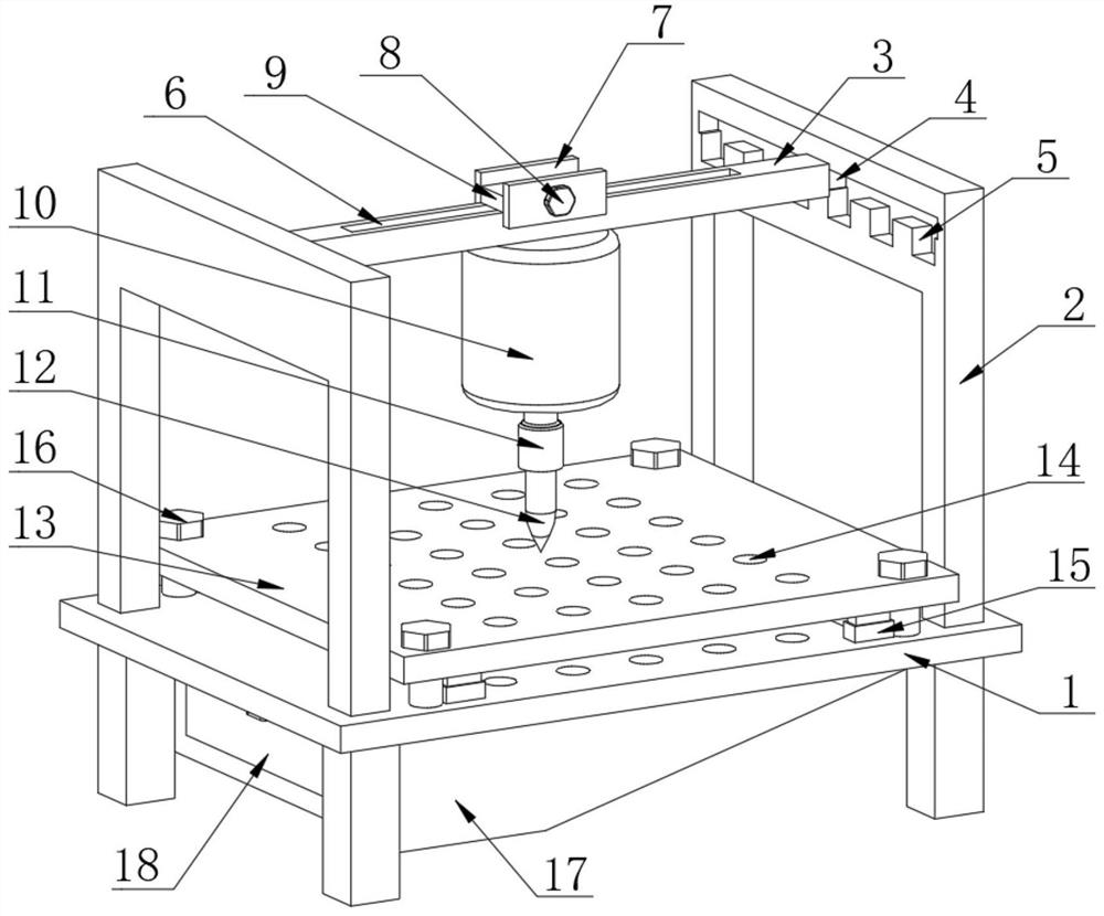
[0003] The operation of electrical equipment is inseparable from electrical accessories. The processing of electrical accessories requires the use of electrical drilling devices, but the existing electrical drilling devices, because most of the electrical accessories are metal, and the fixation is not very stable. During the process, the metal fittings are easily deformed and even broken, resulting in a certain loss. At the same time, the position of the punching hole is not very accurate, which brings some troubles to the user.

Method used


Image

  • Electrical perforating device for electrical construction and using method
  • Electrical perforating device for electrical construction and using method
  • Electrical perforating device for electrical construction and using method

Examples


Embodiment Construction

[0031] In order to enable those skilled in the art to better understand the technical solutions in the present application, the technical solutions in the embodiments of the present application will be clearly and completely described below in conjunction with the drawings in the embodiments of the present application. Obviously, the described The embodiments are only some of the embodiments of the present application, but not all of them. Based on the embodiments in this application, all other embodiments obtained by persons of ordinary skill in the art without creative efforts shall fall within the scope of protection of this application.

[0032] Key terms appearing in this application are explained below.

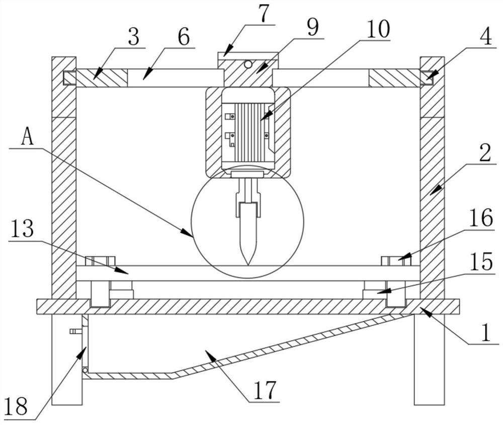
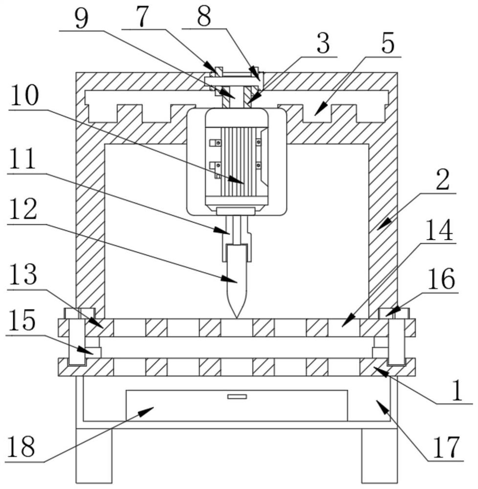
[0033] The electrical punching device for electrical construction provided by the application includes a table body 1, and the upper part of the table body 1 is provided with a limiting plate 13. Both the table body 1 and the limiting plate 13 are rectangular flat struc...


PUM


Abstract

The invention provides an electrical perforating device for electrical construction and a using method. The electrical perforating device comprises a table body, wherein a limiting plate is arranged on the upper portion of the table body and is parallel to the table body, and a distance adjusting component is arranged between the table body and the limiting plate; supporting frames are arranged atthe two ends of the top of the table body, a movable transverse plate is arranged between the two supporting frames, the movable transverse plate is in sliding connection with the supporting frames,and first limiting components are arranged between the movable transverse plate and the supporting frames; and a movable rod is arranged on the movable transverse plate, the movable rod is slidably connected with the movable transverse plate, a second limiting piece is arranged between the movable rod and the movable transverse plate, a motor is arranged at the bottom of the movable rod, a rotating sleeve is arranged at the output end of the motor, a drill bit is arranged at the bottom of the rotating sleeve, and the rotating sleeve is in threaded connection with the drill bit. The electricalperforating device for electrical construction is reasonable in structure and convenient to operate, avoids loss caused by deformation and even breakage of metal accessories in a perforating process,improves the use safety and accuracy and saves the cost.

Description

technical field [0001] The present application relates to the technical field of electrical drilling, in particular to an electrical drilling device for electrical construction and a method of use. Background technique [0002] Electricity is a general term for disciplines or engineering fields such as the production, transmission, distribution, use, and electrical equipment manufacturing of electrical energy. It is a science that uses electrical energy, electrical equipment, and electrical technology to create, maintain, and improve limited spaces and environments. Three aspects of electric energy conversion, utilization and research, including basic theory, application technology, facilities and equipment, etc. Electrical equipment is a general term for generators, transformers, power lines, circuit breakers and other equipment in the power system. The most critical factor for operation and delivery is the electrical equipment. [0003] The operation of electrical equipme...

Claims


Application Information

Patent Timeline
Patent Type & Authority Applications(China)
IPC IPC(8): B23B39/14B23B41/00B23B47/00B23Q3/06B23Q11/00
CPCB23B39/14B23B41/00B23B47/00B23Q3/062B23Q11/0067
Inventor 伊西娟高胜宝梁爽李玉国徐兴娣陈敬华韩伟尧宁玉波姜志蓬陈亚丽张兰燕王瑜李慧丛普庆刘宇鹏刘锦超
Owner 国网山东省电力公司昌邑市供电公司
Learn More