
A Quick Installation Method for Horizontal Furnace Tube

An installation method and horizontal furnace technology, applied in the direction of furnaces, furnace components, furnace crowns/roofs, etc., can solve the problems of reduced safety and stability of furnace wall steel structures, inability to cross operations, and difficult construction, and achieve low construction difficulty, The effect of avoiding compression deformation and saving construction progress

Active Publication Date: 2022-06-07
CHINA CHENGDA ENG
View PDF8 Cites 0 Cited by
  • Summary
  • Abstract
  • Description
  • Claims
  • Application Information

AI Technical Summary

Problems solved by technology

[0003] At present, there are many installation methods for horizontal furnace tubes, but some methods have potential safety hazards, some methods are more difficult to construct, and some methods cannot be cross-operated to affect the progress
For example, in some existing furnace tube installation methods, since the weight of the furnace tube hanger is borne by the bottom of the furnace, the upper part is only temporarily limited and has no hanging point, and the end wall on one side is all open to facilitate the feeding of the tube row Therefore, the safety and stability of the steel structure of the furnace wall in the entire radiant section is greatly reduced, and the bottom of the furnace will bear all the weight of the hanger and the entire tube row, and the deformation of the bottom of the furnace is relatively large

Method used


Image

  • A Quick Installation Method for Horizontal Furnace Tube
  • A Quick Installation Method for Horizontal Furnace Tube

Examples


Embodiment Construction

[0021] In order to make the purposes, technical solutions and advantages of the embodiments of the present invention clearer, the technical solutions in the embodiments of the present invention will be clearly and completely described below with reference to the accompanying drawings in the embodiments of the present invention. Obviously, the described embodiments These are some embodiments of the present invention, but not all embodiments. The components of the embodiments of the invention generally described and illustrated in the drawings herein may be arranged and designed in a variety of different configurations.

[0022] Thus, the following detailed description of the embodiments of the invention provided in the accompanying drawings is not intended to limit the scope of the invention as claimed, but is merely representative of selected embodiments of the invention. Based on the embodiments of the present invention, all other embodiments obtained by those of ordinary ski...


PUM


Abstract

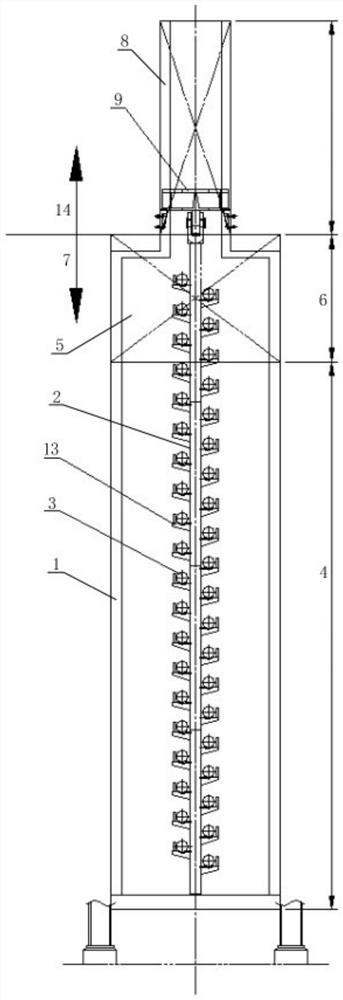
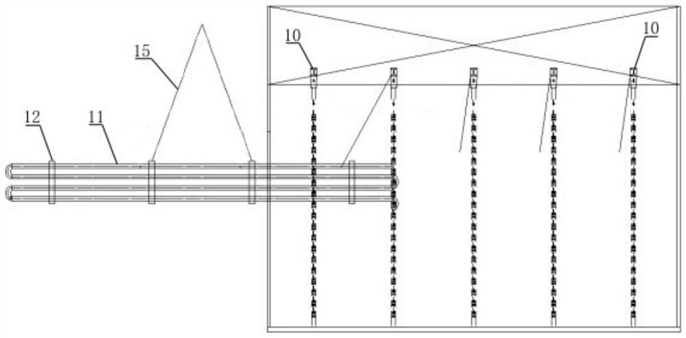
The invention discloses a quick installation method of a horizontal furnace tube. By using the hanger beam of the convection section module, before installing the furnace tube row, the furnace tube hanger in the furnace body is suspended in advance, and then the furnace tube The tube row is fed horizontally and installed on the furnace tube hanger. Compared with the existing structural design supported on the bottom of the furnace, it can effectively avoid the deformation of the bottom of the furnace under pressure, thereby facilitating the subsequent construction of refractory materials. Before installation, the furnace body can form a basically complete box body, and the structural stability is guaranteed. The installation of the furnace tube in the radiant section is also in place at one time, which is convenient for on-site construction, and can also avoid the deviation of the small tube row caused by the second lifting of the furnace tube. oblique risk. The invention has the characteristics of low construction difficulty and low risk, and simultaneously saves construction progress.

Description

technical field [0001] The invention belongs to the technical field of furnace tube installation in chemical equipment, and particularly relates to a rapid installation method for a horizontal furnace tube in a radiant section in a tubular square box furnace. Background technique [0002] At present, VCM and PVC projects are in the ascendant. About 95% of the world's EDC is used to produce VCM. As the current mainstream process of ethylene process, the EDC cracking furnace is the front-end core equipment in the VCM plant. As an important part of the installation of this equipment, the horizontal furnace The rationality of the construction method in the process of tube installation is related to the progress and safety of the entire installation work. High-quality furnace tube installation can also ensure the service life of the furnace tube. [0003] At present, there are many installation methods for horizontal furnace tubes, but some methods have potential safety hazards, ...

Claims


Application Information

Patent Timeline
Patent Type & Authority Patents(China)
IPC IPC(8): B66C13/08B66C1/10C07C17/25C07C21/06F27D1/02
CPCB66C13/08B66C1/10C07C17/25F27D1/021C07C21/06Y02P20/10
Inventor 雷勇刘斌沈结李国龙迟祥李魅程鑫高文娟
Owner CHINA CHENGDA ENG
Learn More