Horizontal scanning pulse signal control circuit using digital circuit

A technology of pulse signal and horizontal scanning, which is applied in the direction of automatic power control, TV system scanning details, pulse generation, etc., and can solve problems such as image size influence

Inactive Publication Date: 2003-10-01
NEC ELECTRONICS CORP
View PDF0 Cites 0 Cited by
  • Summary
  • Abstract
  • Description
  • Claims
  • Application Information

AI Technical Summary

Problems solved by technology

[0003] However, in the above-mentioned horizontal scanning pulse signal control circuit of the prior art, the slope of the sawtooth wave signal is directly affected by the performance of various components of the sawtooth wave generating circuit. These components include capacitors and resistors, which change the pulse of the horizontal scanning pulse signal. wide, thus adversely affecting the size of the image displayed on the screen

Method used


Image

  • Horizontal scanning pulse signal control circuit using digital circuit
  • Horizontal scanning pulse signal control circuit using digital circuit
  • Horizontal scanning pulse signal control circuit using digital circuit

Examples


Embodiment Construction

[0023] Before describing the preferred embodiment of the present invention, the prior art will be described with reference to FIGS.

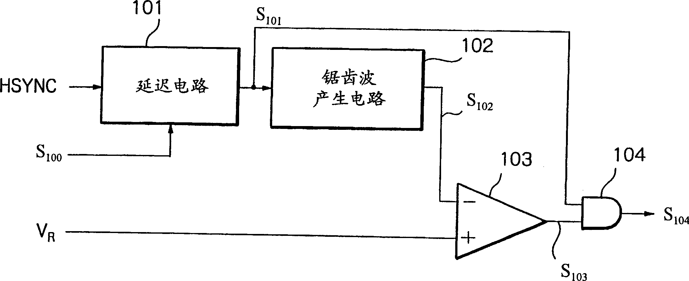
[0024] In FIG. 1 showing a prior art horizontal scanning pulse signal control circuit, reference numeral 101 denotes a delay circuit for receiving a horizontal synchronizing signal HSYNC and generating a delayed pulse signal S101 according to a horizontal position control voltage signal S100.

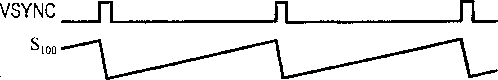
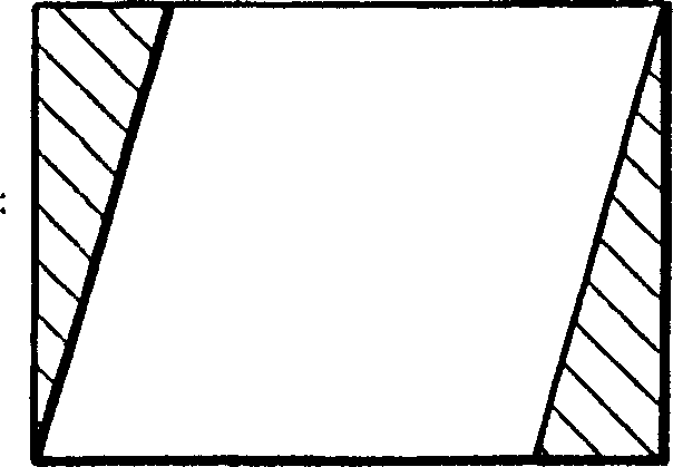
[0025] The horizontal position control voltage signal S100 uses a deflection correction waveform to determine the horizontal phase. For example, if the horizontal position control voltage signal S100 is a vertical synchronous sawtooth signal as shown in FIG. 2A , then the horizontal phase shift is synchronized with the vertical synchronous signal VSYNC, so that the displayed image is corrected as shown in FIG. 2B . On the other hand, if the horizontal position control voltage signal S100 is a vertical synchronous parabolic wave signal as shown in FIG. 3A,...


PUM


Abstract

A horizontal scanning pulse signal control circuit comprises: a reference clock generation circuit; first and second horizontal position reference pulse generation circuits connected with the reference clock generation circuit; first and second horizontal position reference pulse generation circuits connected with the first and second horizontal position reference pulse generation circuits and the second sawtooth wave generation circuit; the first and second comparators connected to the first and second sawtooth wave generation circuits compare the sawtooth wave signal with the horizontal position selection voltage to generate a comparison signal; and the first and second The RS flip-flop connected to the comparator is set and reset by the first and second comparison signals respectively, and the output signal of the RS flip-flop is used as a horizontal scanning pulse signal.

Description

technical field [0001] The present invention relates to a horizontal scan pulse signal control circuit used in a multi-scan type display device suitable for a plurality of different frequencies. Background technique [0002] The horizontal scan pulse signal control circuit in the prior art includes a delay circuit for receiving a horizontal synchronous signal to generate a delay pulse signal according to a horizontal position control voltage signal, a sawtooth wave generation circuit for generating a sawtooth wave signal, and a sawtooth wave signal for generating a sawtooth wave signal. A comparator for comparing with the pulse width selection voltage, and an AND circuit connected with the comparator and the delay circuit for generating horizontal scanning pulse signals. This will be described in detail later. [0003] However, in the above-mentioned horizontal scanning pulse signal control circuit of the prior art, the slope of the sawtooth wave signal is directly affected...

Claims


Application Information

Patent Timeline
Patent Type & Authority Patents(China)
IPC IPC(8): H04N3/223G09G1/04G09G1/16H03K4/06H03L7/06H04N3/22H04N3/227H04N3/23
CPCG09G1/04H03L7/06H04N3/22H04N3/16
Inventor 川住隆文
Owner NEC ELECTRONICS CORP
Why Eureka
Try Eureka