Integrated 'leading-blocking-guiding' multifunctional temporary ecological drainage device and method

A multi-functional and temporary technology, applied in water conservancy projects, hydropower, hydropower stations, etc., can solve the problems of greater ecological impact on the downstream, long ecological cut-off time of downstream rivers, and ecological water supply, etc., so as to reduce engineering costs and reduce Influence and reduce the effect of steel pipe length

Inactive Publication Date: 2021-02-05
CHANGJIANG SURVEY PLANNING DESIGN & RES
View PDF5 Cites 0 Cited by
  • Summary
  • Abstract
  • Description
  • Claims
  • Application Information

AI Technical Summary

Problems solved by technology

[0006] 2. A single pre-embedded steel pipe is used to conduct water, and the ecological cut-off time of the downstream river is long;
However, for projects where the diversion tunnel plugging body is far away from the inlet gate, dozens of steel pipe sections need to be welded, the construction period is about 10 days, and the steel pipe cost is about 500,000 yuan, which means that in the steel pipe welding stage, the upstream reservoir It is impossible to provide ecological water supply to the downstream river, and the downstream river will face a cut-off time of up to 10 days, which will have a great impact on the downstream ecology (Scheme 2)

Method used


Image

  • Integrated 'leading-blocking-guiding' multifunctional temporary ecological drainage device and method
  • Integrated 'leading-blocking-guiding' multifunctional temporary ecological drainage device and method
  • Integrated 'leading-blocking-guiding' multifunctional temporary ecological drainage device and method

Examples


Embodiment Construction

[0043] The following will clearly and completely describe the technical solutions in the embodiments of the present invention with reference to the accompanying drawings in the embodiments of the present invention. Obviously, the described embodiments are only some, not all, embodiments of the present invention.

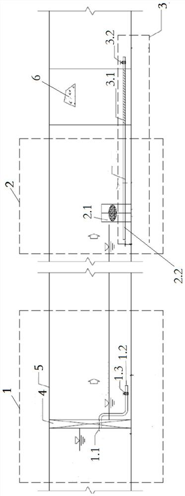
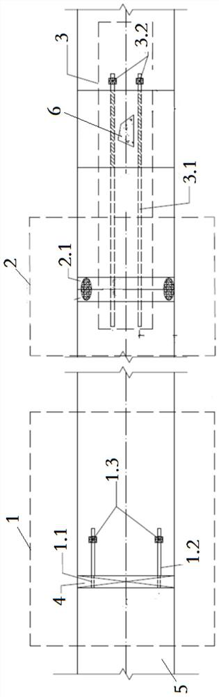
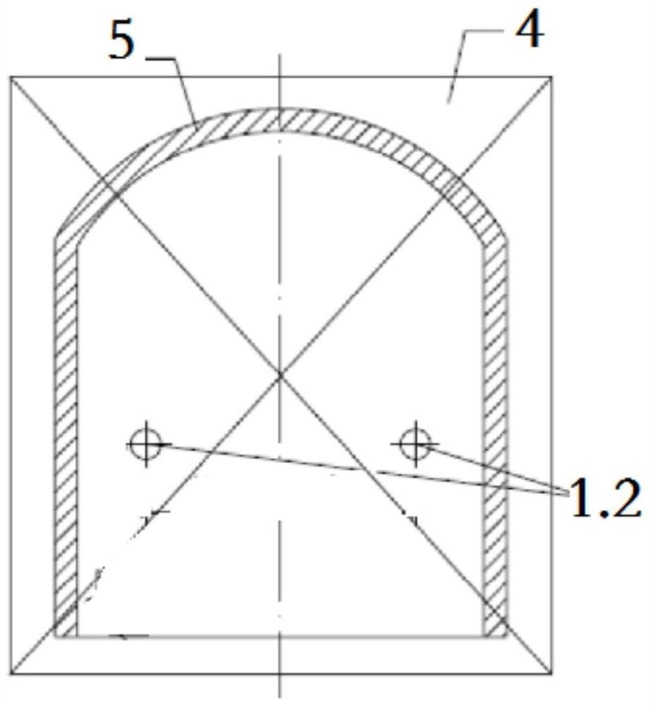
[0044] refer to Figure 1-8 Shown: a multi-functional temporary ecological water release device integrating "leading-blocking-guiding", located in the diversion tunnel 5, the diversion tunnel 5 is provided with a diversion tunnel gate 4 at the front end, and a blocking body 6 at the end ;

[0045]It includes a water diversion device 1, a water blocking device 2 and a water guide device 3 arranged in sequence along the flow direction of the water;

[0046] The water diversion device 1 is composed of a gate reserved hole 1.1, a first section of steel pipe 1.2 and a first gate valve 1.3;

[0047] The two gate reserved holes 1.1 are located at the same height and on th...


PUM


Abstract

The invention discloses an integrated 'leading-blocking-guiding' multifunctional temporary ecological drainage device and method. The integrated 'leading-blocking-guiding' multifunctional temporary ecological drainage device is located in a diversion tunnel (5). A diversion tunnel gate (4) is arranged at the front end of the diversion tunnel (5), and a plugging body (6) is arranged at the tail endof the diversion tunnel. The integrated 'leading-blocking-guiding' multifunctional temporary ecological drainage device comprises a water leading device (1), a water blocking device (2) and a water guiding device (3) which are sequentially arranged in the water flow direction. The water leading device (1) consists of gate preformed holes (1.1), first section steel pipes (1.2) and first gate valves (1.3). The two gate preformed holes (1.1) are formed in the same height and located in the diversion tunnel gate (4), and the first section steel pipes (1.2) are arranged on the gate preformed holes(1.1). According to the integrated 'leading-blocking-guiding' multifunctional temporary ecological drainage device and method, the defects that in the prior art, a single pre-buried steel pipe waterguide mode is adopted, and the ecological cutoff time of a downstream river channel is long are overcome. The integrated 'leading-blocking-guiding' multifunctional temporary ecological drainage deviceand method have the advantages that the ecological cutoff time of the downstream river channel is shortened from 10 days to 1-2 days, and the influence of ecological cutoff on the downstream river channel is effectively reduced.

Description

technical field [0001] The invention relates to the technical field of temporarily discharging ecological flow to downstream rivers during the blockage of diversion tunnels for water conservancy and hydropower, and more specifically relates to a multifunctional temporary ecological water discharge device that integrates "leading-blocking-guiding", that is, a method. Background technique [0002] For water conservancy and hydropower projects, in order to meet the basic ecological needs of the downstream river channel during the storage period of the reservoir, it is necessary to divert the inland river water of the upstream channel reservoir to the downstream channel. [0003] At present, the methods commonly used in engineering mainly include two categories, the first category: using mobile pumps to draw water from the upstream reservoir to the downstream river channel (Scheme 1). Type 2: A single diversion hole is used to block the reserved steel pipe in the body (plan 2), ...

Claims


Application Information

Patent Timeline
Patent Type & Authority Applications(China)
IPC IPC(8): E02B9/00E02B9/06
CPCE02B9/00E02B9/06Y02E10/20
Inventor 闫福根邹德兵肖伟位思佳傅兴安卢增木程子刚曾绍茹胡涛
Owner CHANGJIANG SURVEY PLANNING DESIGN & RES
Why Eureka
Try Eureka