Vacuum pipeline extraction type underwater sludge ship

A vacuum pipeline and extraction technology, which is applied to fixed filter element filters, mechanically driven excavators/dredgers, filtration and separation, etc., can solve the problem of affecting the continuity of mud pumping work, difficulty in collecting mud, and mud pumping equipment is easy to fall into mud medium problem

Inactive Publication Date: 2021-02-05
福州市建金建智能科技有限公司
View PDF0 Cites 0 Cited by
  • Summary
  • Abstract
  • Description
  • Claims
  • Application Information

AI Technical Summary

Problems solved by technology

[0003] The sludge at the bottom of the water will gather together if it exists for too long. If it is not treated in time, it will affect the flow of water sources in the river and affect the water conservancy project. Because the sludge at the bottom of the water has both water and land features, in Under the environment of silt accumulation, part of the garbage is half embedded in the silt, which makes it difficult to collect. The silt pumping equipment is also easy to fall into the silt when it is in use. The existing technology generally directly extracts the silt. Although this method can realize the collection of silt, but The collection process is extremely difficult. At the same time, because the mud at the bottom contains a lot of nutrients, it can be used as fertilizer after simple treatment. If it is collected and discharged directly, it will cause a lot of waste of resources. In particular, due to the large amount of impurities at the bottom of the water, direct Extraction will lead to blockage of the feed inlet. After the filter mechanism is used, a large amount of impurities will adhere to the outer wall of the filter mechanism. If it is not handled in time, it will affect the continuity of the mud pumping work.

Method used


Image

  • Vacuum pipeline extraction type underwater sludge ship
  • Vacuum pipeline extraction type underwater sludge ship
  • Vacuum pipeline extraction type underwater sludge ship

Examples


Embodiment Construction

[0028] The following will clearly and completely describe the technical solutions in the embodiments of the present invention with reference to the accompanying drawings in the embodiments of the present invention. Obviously, the described embodiments are only some, not all, embodiments of the present invention.

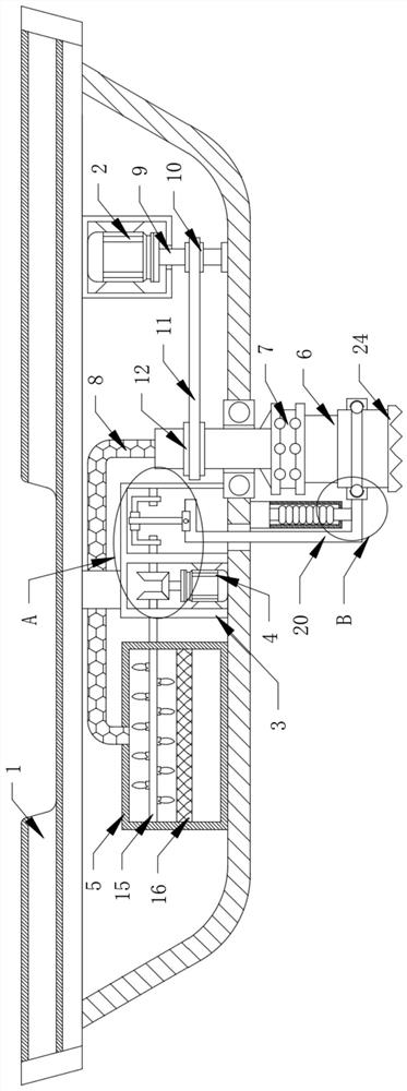
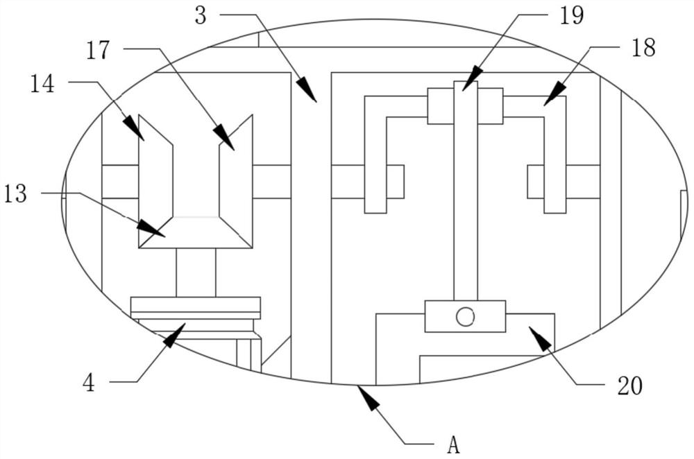
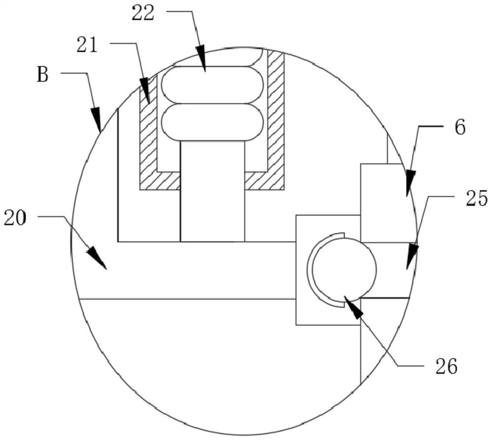
[0029] refer to Figure 1-5 , a vacuum pipeline extraction type underwater mud ship, comprising a hull 1, a first drive motor 2, a fixed frame 3, a second drive motor 4 and a storage box 5, the first drive motor 2 is fixedly connected to the inner wall of the hull 1, The model of the first driving motor 2 is Y80M1-1, the fixed frame 3 is fixedly connected on the lower inner wall of the hull 1, the second driving motor 4 is fixedly connected on the inner wall of the fixed frame 3, and the model of the second driving motor 4 is Y80M2 -1, the material storage box 5 is fixedly connected to the lower inner wall of the hull 1 and is close to the left side of the fixed fram...


PUM


Abstract

The invention discloses a vacuum pipeline extraction type underwater sludge ship which comprises a ship body, a first driving motor, a fixing frame, a second driving motor and a storage box, the firstdriving motor is fixedly connected to the inner wall of the ship body, and the fixing frame is fixedly connected to the inner wall of the lower side of the ship body; and the second driving motor isfixedly connected to the inner wall of the fixing frame, the storage box is fixedly connected to the inner wall of the lower side of the ship body and is close to the left side of the fixing frame, and the inner wall of the lower side of the ship body is inserted into a feeding pipeline. When the vacuum pipeline extraction type underwater sludge ship is used, the effect of crushing materials in advance is achieved through cooperative use of structures such as a sleeve, a rotary cutting wheel and an inner rack, the effect of crushing and recycling sludge is achieved through cooperative use of structures such as a second bevel gear, a stirring blade and a water filtering net, and through cooperative use of structures such as an annular seat, an inserting needle and an isolation net, the effect of automatic impurity removal is achieved.

Description

technical field [0001] The invention belongs to the technical field of silt collection, in particular to a vacuum pipeline extraction type underwater silt ship. Background technique [0002] With the development of the economy, most cities are being developed and constructed. In the process of urban construction, forest land will be reclaimed on a large scale. In rainy days, the reclaimed soil will be washed away by the rain, and the soil will be carried into Hanoi by the rain and sink to the bottom of the river. The silt in the urban river will affect the normal performance of urban flood control, drainage, water supply and other functions. In order to restore the normal function of the river, it is necessary to dredge the river, so that the river will become deeper and wider through treatment, and the river will become clearer. Currently, large-scale silt boats are usually used for dredging urban river silt. [0003] The sludge at the bottom of the water will gather toget...

Claims


Application Information

Patent Timeline
IPC IPC(8): E02F3/88B01D29/01B01D29/76B01D29/94B02C18/06B02C18/16B02C18/24
CPCB01D29/01B01D29/76B01D29/94B02C18/06B02C18/16B02C18/24E02F3/885
Inventor 张秀平
Owner 福州市建金建智能科技有限公司
Why Eureka
Try Eureka