Foaming device of intelligent closestool and intelligent closestool
A technology of intelligent toilet and foaming device, which is applied in the field of bathroom, can solve the problems of large amount of foaming liquid, dry foaming liquid, and poor foaming effect, and achieve the effects of improving quality, prolonging service life, and reducing dosage
- Summary
- Abstract
- Description
- Claims
- Application Information
AI Technical Summary
Problems solved by technology
Method used
Image

Examples
Embodiment Construction
[0027] The present invention will be further described below with specific embodiment, see figure 1 -8:
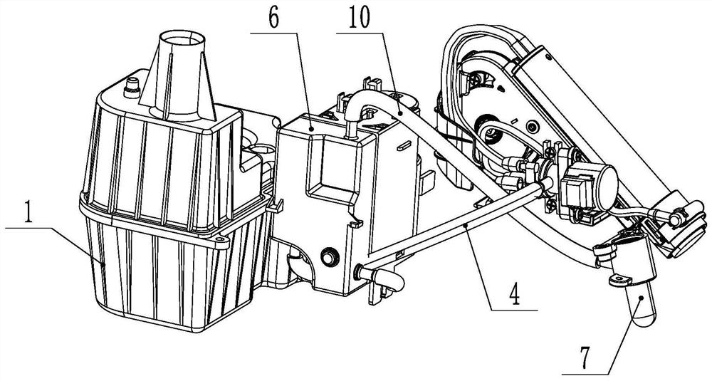
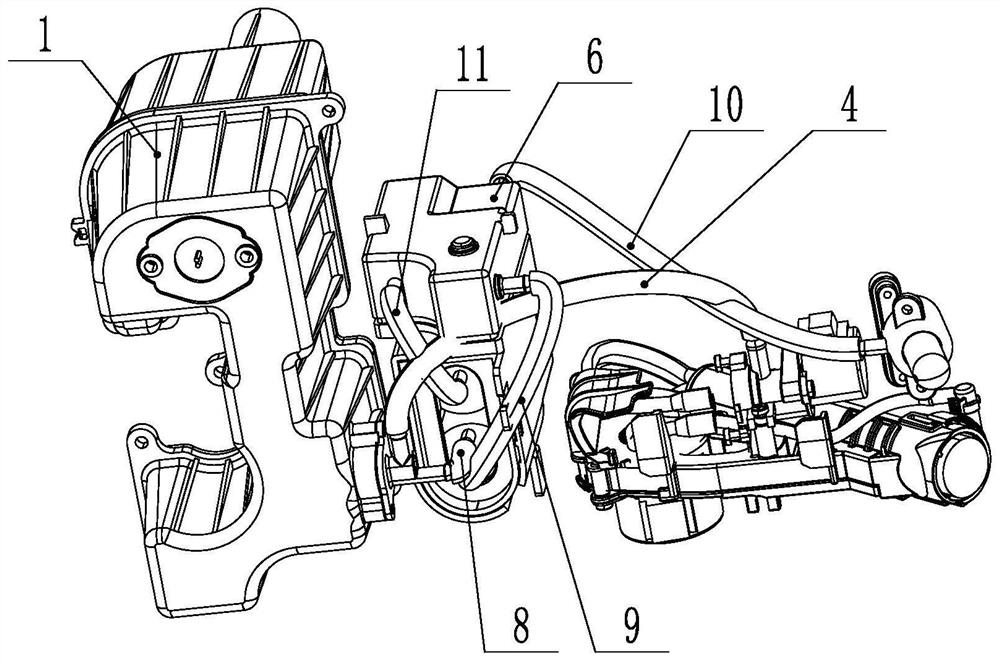
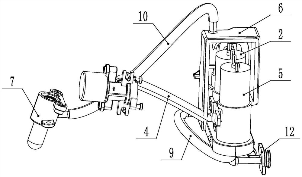
[0028] One of the objects of the present invention is to provide a foaming device for an intelligent toilet, including a liquid filling tank 1, an air pump 2, a foaming box 6 and a nozzle 7. The liquid filling tank 1 is provided with a foaming liquid capable of generating foam, such as dish soap etc. The liquid filling tank 1 is provided with a liquid outlet 3, and the liquid outlet 3 is provided with a one-way valve, and the liquid outlet 3 is connected with the water inlet pipeline 4 and the water inlet of the suction pump 5 respectively, and the pumping The water outlet of the liquid pump 5 is connected to the inlet of the foaming box 6 , the outlet of the foaming box 6 is connected to the nozzle 7 , and the air pump 2 is connected to the foaming box 6 . The spray head 7 of the present invention is a rotary spray head. The water inlet pipeline 4 is connected with the...
PUM
 Abstract
Description
Claims
Application Information
PatSnap Eureka turns technology decisions into work you can execute. Powered by our Innovation Knowledge Graph, it runs expert workflows across engineering, life sciences, materials and intellectual property. Get your review-ready output in minutes.


