
Pedal simulator adjusting fork hole position detection device with automatic righting function

A pedal simulator and self-righting technology, which is applied in the field of inspection and inspection, can solve the problems that it is difficult to meet the stability requirements of the inspection system, the stability control requirements of the manufacturing process, the poor repeatability and reproducibility of the inspection results, and the large differences in the inspection results. Achieving fast detection and output results, avoiding differences in detection results, high repeatability and reproducibility

Pending Publication Date: 2021-02-05
上海拿森汽车电子有限公司
View PDF0 Cites 0 Cited by
  • Summary
  • Abstract
  • Description
  • Claims
  • Application Information

AI Technical Summary

Problems solved by technology

[0004] At present, the detection method combined with a height gauge and a measuring rod is routinely used. The defects of this method include at least: due to the influence of factors such as the processing status of each component part and the difference in the measurement operator's technique, the detection results are quite different, and the detection results are repeated. Poor performance and reproducibility, it is difficult to meet the stability requirements of the detection system and the stability control requirements of the manufacturing process

Method used


Image

  • Pedal simulator adjusting fork hole position detection device with automatic righting function
  • Pedal simulator adjusting fork hole position detection device with automatic righting function
  • Pedal simulator adjusting fork hole position detection device with automatic righting function

Examples


Embodiment Construction

[0033] The technical solution of the present invention will be further described below in conjunction with the accompanying drawings and through specific implementation methods.

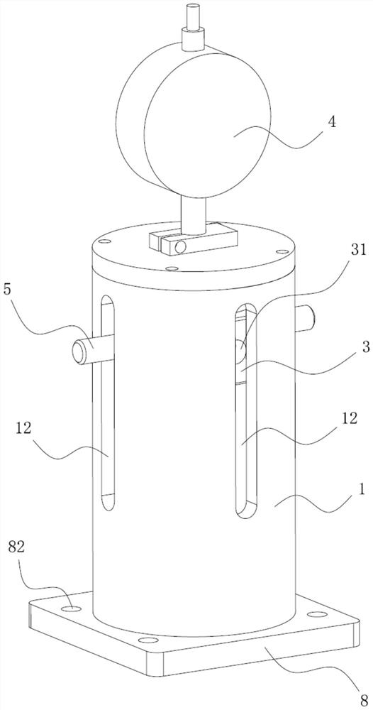
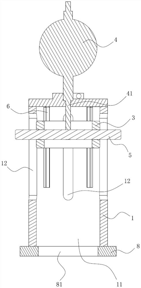
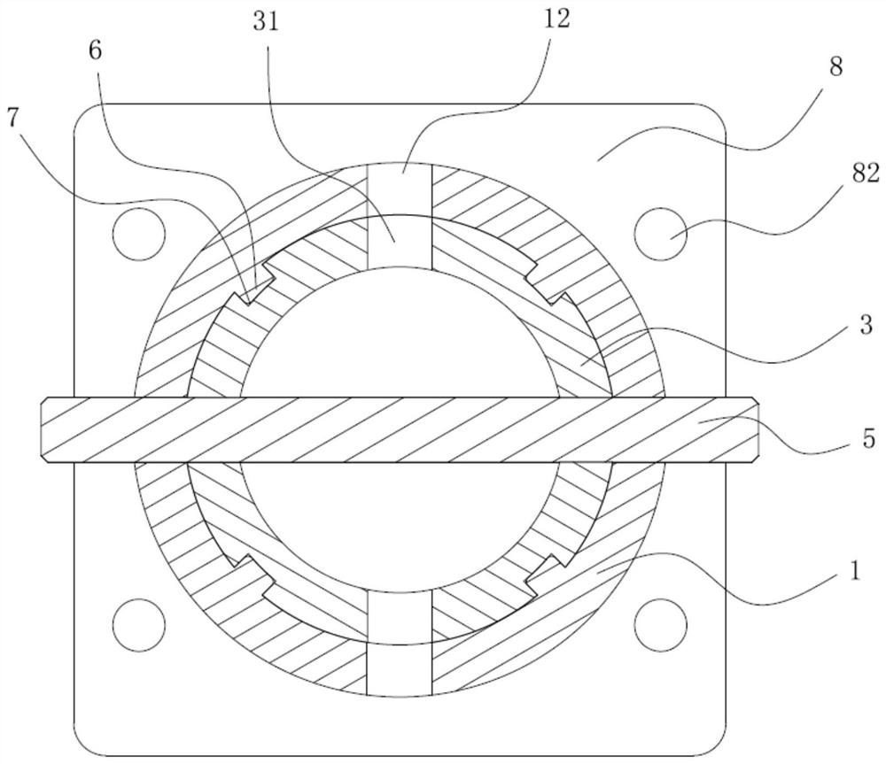
[0034] The embodiment discloses a pedal simulator adjustment fork hole position detection device with an automatic righting function and a pedal simulator adjustment fork hole position detection method based on the detection device. like Figure 1 to Figure 6 As shown, the detection device includes a hollow cylindrical casing 1, the bottom of the casing 1 is provided with a casing opening 11 for the entry and exit of the part 2 to be detected, and the side wall is provided with a measuring groove 12 extending axially along the casing 1. The measuring groove 12 Preferably it is a long hole. A guide slider 3 is arranged inside the casing 1 , and a measuring hole 31 is arranged on the side wall of the guide slider 3 . The guide slider 3 is configured to move along the axis of the casing 1 but not to ro...


PUM


Abstract

The invention discloses a pedal simulator adjusting fork hole position detection device with an automatic righting function, belongs to the technical field of detection and inspection in assembly andmanufacturing, and is designed for solving the problems of poor detection result stability and the like in the prior art. The pedal simulator adjusting fork hole position detection device with the automatic righting function comprises a shell, wherein a measuring groove is formed in the side wall of the shell; a guide sliding block is arranged in the shell, a measuring hole is formed in the guidesliding block, and the guide sliding block is configured to move along the axis of the shell but cannot rotate relative to the shell; a measuring rod of a dial indicator extends into the shell; a measuring pin can penetrate through the measuring groove, the measuring hole and the central hole of the adjusting fork of the to-be-detected piece, and the end of the measuring rod abuts against the measuring pin or is connected to the measuring pin. According to the pedal simulator adjusting fork hole position detection device with the automatic righting function, the adjusting fork hole position can be detected more quickly and accurately, and the detection result difference caused by operation factors and measurement methods is avoided.

Description

technical field [0001] The invention relates to the technical field of detection and inspection in assembly and manufacturing, in particular to a pedal simulator adjustment fork hole position detection device with an automatic righting function and a pedal simulator adjustment fork hole position detection method. Background technique [0002] A car is an efficient means of transportation, using electric energy, gasoline or diesel to drive the wheels to rotate. Drivers often need to use pedals when manipulating the car, and in cars with a high degree of electronics, a pedal simulator is usually installed. [0003] Most of the existing pedal simulators use a pure spring solution, and some use a spring + rubber solution. Regardless of the above-mentioned solutions, it is necessary to detect the adjustment fork hole position of the pedal simulator in the electronic power-assisted braking system relying on spring return during the manufacturing process, so as to ensure the assem...

Claims


Application Information

Patent Timeline
IPC IPC(8): G01B5/00G01B5/02G01B5/14
CPCG01B5/0025G01B5/02G01B5/14
Inventor 陶喆刘海珍张日波朱心放范鹏刘倩
Owner 上海拿森汽车电子有限公司
Learn More