Supercharge Your Innovation With Domain-Expert AI Agents!

Detection method and device based on ultrasonic radar and vehicle

A detection method, ultrasonic technology, applied in the field of vehicles, can solve the problems affecting the parking path, the shape of the virtual parking space does not match, the edge error of the obstacle, etc., and achieve the effect of improving driving safety and driving experience

Pending Publication Date: 2021-02-05
GUANGZHOU XIAOPENG CONNECTIVITY TECH CO LTD
View PDF0 Cites 0 Cited by
  • Summary
  • Abstract
  • Description
  • Claims
  • Application Information

AI Technical Summary

Problems solved by technology

[0003] However, during the parking process, the ultrasonic radar will continue to be used to detect the edge information of the parking space, thereby adjusting the parking path. However, due to the lack of directionality of the detection of the ultrasonic radar during the process of the vehicle entering the parking space (warehousing), its default detection point position The location is facing the direction of the ultrasonic radar. Since the vehicle needs to constantly adjust the angle and position to drive into the parking space in general, the angle between the vehicle and the parking space is always changing. The real ultrasonic radar The detection echo may be radiated waves from different angles. If the default echo is the detection point in the direction facing the ultrasonic radar, it will cause a large error in the edge of the obstacle detected by the ultrasonic radar, resulting in the shape of the virtual parking space. It does not match the shape of the actual parking space, thus affecting the generation of the parking path, which may make the final parking position of the vehicle close to the side of the parking space or stop parking directly
When the position error of the detection point position of the ultrasonic radar is large, the detection result of obstacles is affected, which in turn affects the driving experience of the driver.

Method used


Image

  • Detection method and device based on ultrasonic radar and vehicle
  • Detection method and device based on ultrasonic radar and vehicle
  • Detection method and device based on ultrasonic radar and vehicle

Examples


Embodiment Construction

[0037] In order to make the above objects, features and advantages of the present invention more comprehensible, the present invention will be further described in detail below in conjunction with the accompanying drawings and specific embodiments. Apparently, the described embodiments are some, but not all, embodiments of the present invention. Based on the embodiments of the present invention, all other embodiments obtained by persons of ordinary skill in the art without creative efforts fall within the protection scope of the present invention.

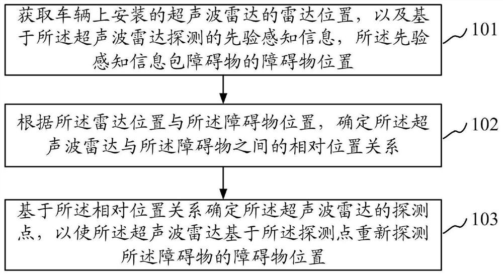
[0038] refer to figure 1 , which shows a flow chart of the steps of a detection method based on ultrasonic radar provided by an embodiment of the present invention, which may specifically include the following steps:

[0039] Step 101, acquire the radar position of the ultrasonic radar installed on the vehicle, and the prior perception information detected based on the ultrasonic radar, the prior perception information includes th...


PUM


Abstract

The embodiment of the invention provides a detection method based on an ultrasonic radar and a vehicle, and the method comprises the steps: acquiring the radar position of an ultrasonic radar installed on the vehicle, and priori perception information based on the detection of the ultrasonic radar, wherein the priori perception information comprises the obstacle position of an obstacle; determining a relative position relationship between the ultrasonic radar and the obstacle according to the radar position and the obstacle position; and determining a detection point position of the ultrasonicradar based on the relative position relationship, thus enabling the ultrasonic radar to re-detect the obstacle position of the obstacle based on the detection point position. In the embodiment of the invention, the detection point position of the ultrasonic radar is adjusted based on the relative position relationship between the ultrasonic radar and the obstacle, so that the obstacle position of the obstacle is detected again based on the adjusted detection point position, the driving safety is improved, and the driving experience of a driver is improved.

Description

technical field [0001] Embodiments of the present invention relate to the technical field of vehicles, in particular to a detection method, device and vehicle based on ultrasonic radar. Background technique [0002] At present, vehicles with automatic driving functions are usually equipped with ultrasonic radar. The ultrasonic radar detects the driving environment, such as the detection of the edge information of the parking space, so that the parking space information of the parking space is virtually generated based on the edge information of the parking space, so that it can be based on the parking space. The information generates a parking path for parking. [0003] However, during the parking process, the ultrasonic radar will continue to be used to detect the edge information of the parking space, thereby adjusting the parking path. However, due to the lack of directionality of the detection of the ultrasonic radar during the process of the vehicle entering the parking...

Claims


Application Information

Patent Timeline
IPC IPC(8): G01S15/931B60W30/06
CPCG01S15/931B60W30/06B60W2552/50B60W2420/408
Inventor 张鸿欧阳湛秦汉蒋少峰陈盛军
Owner GUANGZHOU XIAOPENG CONNECTIVITY TECH CO LTD
Features
  • R&D
  • Intellectual Property
  • Life Sciences
  • Materials
  • Tech Scout
  • Unparalleled Data Quality
  • Higher Quality Content
  • 60% Fewer Hallucinations
Learn More