
A leakage protection device

A technology of leakage protection device and leakage protector, which is applied in substation/distribution device casing, cooling/ventilation of substation/switchgear, details of substation/switch layout, etc., which can solve unfavorable leakage protector waterproof and installation cabinet Problems such as high probability of electric shock, moisture leakage of equipment, etc., achieve the effect of reducing the demand for heat dissipation and power supply, preventing equipment from moisture leakage, and ensuring normal use

Active Publication Date: 2022-06-21
中铝智能数维(杭州)工程设计研究院有限公司 +1
View PDF14 Cites 0 Cited by
  • Summary
  • Abstract
  • Description
  • Claims
  • Application Information

AI Technical Summary

Problems solved by technology

[0003] When the leakage protector is used, it is not convenient to protect the line ends. If it is affected by external water vapor, it will easily affect the normal use of the leakage protector. The impact of the influence of the installation cabinet makes the electric shock probability of the installation cabinet higher, and the leakage protection of a single leakage protector is not convenient to fully guarantee the overall leakage protection. Due to the heat dissipation requirements of the installation cabinet, multiple cooling slots or cooling holes are generally designed on the cabinet. , when rainwater occurs, it is easy to enter the inside of the installation cabinet from the cooling hole, which is not conducive to the waterproof performance of the leakage protector, and it is easy to make the equipment damp and cause leakage

Method used


Image

  • A leakage protection device
  • A leakage protection device
  • A leakage protection device

Examples


Embodiment Construction

[0028] The technical solutions in the embodiments of the present invention will be clearly and completely described below with reference to the accompanying drawings in the embodiments of the present invention. Obviously, the described embodiments are only a part of the embodiments of the present invention, but not all of the embodiments.

[0029] In the description of the present invention, it should be understood that the terms "upper", "lower", "front", "rear", "left", "right", "top", "bottom", "inside", " The orientation or positional relationship indicated by "outside" is based on the orientation or positional relationship shown in the accompanying drawings, and is only for the convenience of describing the present invention and simplifying the description, rather than indicating or implying that the indicated device or element must have a specific orientation, so as to The specific orientation configuration and operation are therefore not to be construed as limitations of...


PUM


Abstract

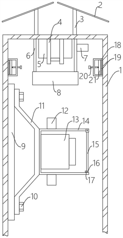
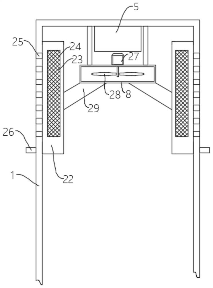
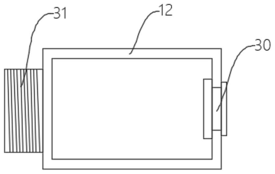
The invention discloses an electric leakage protection device, which comprises an installation cabinet body, an installation bracket and an electric leakage protector. The installation bracket is fixed on the installation cabinet, a protective cover is fixed on the installation bracket, and a Leakage protector, the two ends of the protective cover are fixed with threading pipes, the upper end of the installation cabinet is fixed with two symmetrical installation frames, and photovoltaic panels are installed on the two installation frames, and the installation A support frame is fixed on the inner top wall of the cabinet. The invention detects the humidity in the installation cabinet through the humidity detection device. When the humidity exceeds the limit value, the humidity controller controls the heating belt to heat the installation cabinet, thereby increasing the evaporation speed of water vapor in the installation cabinet, and cooperates with the cooling fan Then the water vapor can be discharged through the dust-proof net, thereby reducing the humidity value in the installation cabinet, better preventing the equipment from being damp and leaking electricity, and ensuring the normal use of the leakage protector.

Description

technical field [0001] The invention relates to the technical field of leakage protection, in particular to a leakage protection device. Background technique [0002] In many outdoor point-of-use equipment, leakage problems are prone to occur due to the influence of the external environment and air humidity. Therefore, leakage protection devices need to be installed. The general leakage protection devices are mainly leakage protectors; [0003] When the leakage protector is used, it is inconvenient to protect the end of the line. If it is affected by external water vapor, it is easy to affect the normal use of the leakage protector. At the same time, the equipment in the cabinet where the leakage protector is installed is vulnerable to moisture leakage. The impact of the installation of the cabinet makes the probability of electric shock higher, and the leakage protection of a single leakage protector is not convenient to fully ensure the overall leakage protection. Due to t...

Claims


Application Information

Patent Timeline
Patent Type & Authority Patents(China)
IPC IPC(8): H02B1/30H02B1/28H02B1/32H02B1/56
CPCH02B1/30H02B1/28H02B1/32H02B1/565
Inventor 权昆程福友尚锐刘标安伟邱勇任向前王玉甫冯寸寸贾强
Owner 中铝智能数维(杭州)工程设计研究院有限公司
Learn More