
Urinary surgery cleaning system

A cleaning system and urology technology, applied in the field of urology cleaning system, can solve the problems of targeted cleaning of diseased parts, delay of operation time, single working mode, etc., and achieve the effect of accelerated reflux, simple operation and convenient use

Active Publication Date: 2021-02-09
刘源
View PDF15 Cites 4 Cited by
  • Summary
  • Abstract
  • Description
  • Claims
  • Application Information

AI Technical Summary

Problems solved by technology

[0004] The purpose of the present invention is to solve the disadvantages that the existing cleaning equipment cannot perform targeted cleaning on the diseased position due to the single working mode when performing cleaning work, and it is time-consuming and laborious, which delays the operation time. A cleaning system for urology

Method used


Image

  • Urinary surgery cleaning system
  • Urinary surgery cleaning system
  • Urinary surgery cleaning system

Examples


Embodiment 1

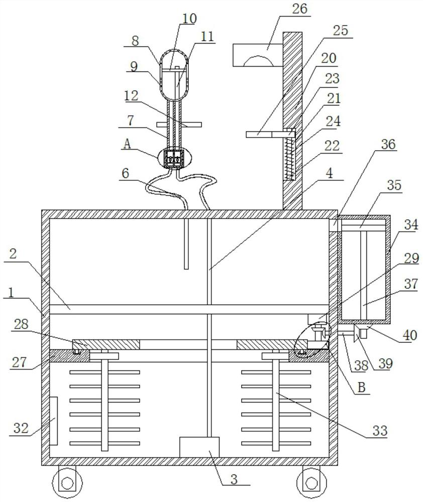
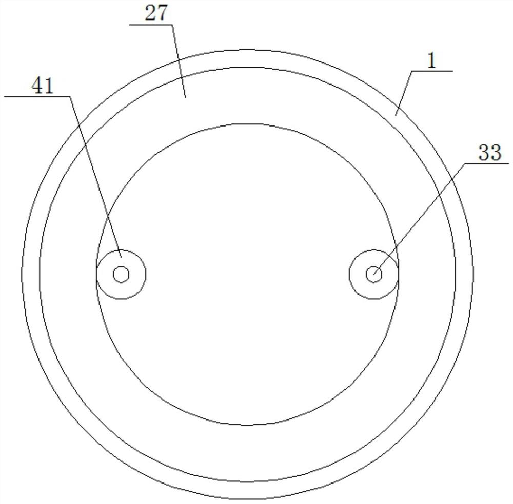
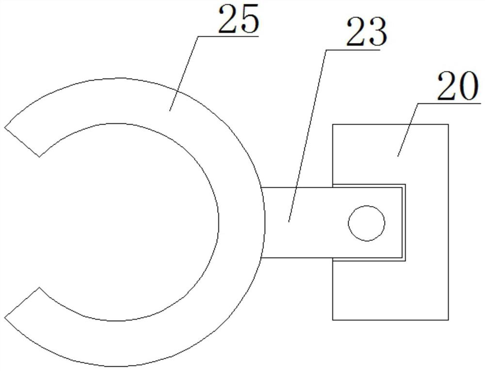
[0027] refer to Figure 1-5 , a cleaning system for urology, comprising a box body 1, a partition plate 2 is fixedly installed on the inner wall of the box body 1, a water pump 3 is fixedly installed on the bottom inner wall of the box body 1, and an outlet pipe 4 is connected to the water pump 3, the box body The outer side of the body 1 is provided with a fixed seat 5, and the fixed seat 5 is connected with two water guide pipes 6, one end of one water guide pipe 6 in the two water guide pipes 6 is fixedly connected with the water outlet pipe 4, and the other water guide pipe 6 is connected with the box body The top inner wall of 1 is connected, and two water guide chambers 13 are respectively connected with two water guide pipes 6 on the fixed seat 5. The inner walls of the two water guide chambers 13 are rotatably connected with the same first rotating rod 14. On the inner wall of each water guide cavity 13, fixed rod 17 is fixedly installed, and second rotating rod 18 is ...

Embodiment 2

[0036] refer to Figure 1-5 , a cleaning system for urology, comprising a box body 1, a partition plate 2 is welded on the inner wall of the box body 1, a water pump 3 is fixed on the bottom inner wall of the box body 1 by bolts, and an outlet pipe 4 is connected to the water pump 3, the box body The outer side of the body 1 is provided with a fixed seat 5, and the fixed seat 5 is connected with two water guide pipes 6, one end of one water guide pipe 6 in the two water guide pipes 6 is fixedly connected with the water outlet pipe 4, and the other water guide pipe 6 is connected with the box body The top inner wall of 1 is connected, and two water guide chambers 13 are respectively connected with two water guide pipes 6 on the fixed seat 5. The inner walls of the two water guide chambers 13 are rotatably connected with the same first rotating rod 14. The inner walls of the water guide chambers 13 are all welded with fixed rods 17, the fixed rods 17 are rotatably connected with...


PUM


Abstract

The invention belongs to the technical field of medical equipment, particularly relates to a urinary surgery cleaning system, and aims at solving the problems that when existing cleaning equipment conducts cleaning work, due to the fact that the working mode is single, the diseased position cannot be well cleaned in a targeted mode, time and labor are wasted, and operation time is delayed. The urinary surgery cleaning system comprises a box body, wherein a partition plate is fixedly mounted on the inner wall of the box body, a water pump is fixedly mounted on the inner wall of the bottom of the box body, a water outlet pipe is connected to the water pump, a fixing base is arranged on the outer side of the box body, two water guide pipes are connected to the fixing base, one end of one of the two water guide pipes is fixedly connected with the water outlet pipe, and the other water guide pipe communicates with the inner wall of the top of the box body. The urinary surgery cleaning system is simple to operate and convenient to use, can clean key positions of a patient, can recycle waste liquid, can heat cleaning liquid, and is convenient for people to use.

Description

technical field [0001] The invention relates to the technical field of medical equipment, in particular to a urology cleaning system. Background technique [0002] Urology is a hospital department that mainly diagnoses and treats some diseases of the "surgery" of the urinary system. It mainly treats various urinary diseases. When performing operations on patients, urology often needs to clean internal organs. [0003] At present, due to the complexity of the human body structure, when the existing cleaning equipment performs cleaning work, due to the single working mode, it cannot perform targeted cleaning on the diseased position well, and it is time-consuming and laborious, which delays the operation time. Therefore, we propose a A urological cleaning system. Contents of the invention [0004] The purpose of the present invention is to solve the disadvantages that the existing cleaning equipment cannot perform targeted cleaning on the diseased position due to the single...

Claims


Application Information

Patent Timeline
Patent Type & Authority Applications(China)
IPC IPC(8): A61M3/02
CPCA61M3/0204A61M3/0208A61M3/0266A61M3/0279
Inventor 刘源
Owner 刘源
Learn More