Self-circulation gas-liquid two-phase flow phase change heat exchanger

A phase change heat exchanger, gas-liquid two-phase flow technology, applied in indirect heat exchangers, lighting and heating equipment, etc., can solve the influence of the working performance of heat pipe heat exchangers and limit the heat transfer capacity of heat pipe heat exchangers and other problems, to achieve the effect of enhancing condensation heat transfer capacity, reducing mutual influence and smooth working fluid circulation

Active Publication Date: 2016-11-23
南京艾科美热能科技有限公司 +1
View PDF6 Cites 12 Cited by
  • Summary
  • Abstract
  • Description
  • Claims
  • Application Information

AI Technical Summary

Problems solved by technology

[0004] At present, the structure of the liquid-absorbing core in the gas-liquid phase change space of the traditional heat pipe heat exchanger is generally provided with grooves, sintered porous metal, attached wire mesh, etc. on the inner wall of the cavity. However, in the practical application of heat pipe heat exchangers, more common heat transfer limits such as capillary limit and carry limit are still relatively easy to occur, which limits the heat transfer performance of heat pipe heat exchangers to a certain extent. Thermal capacity, especially the working performance of heat pipe heat exchangers under anti-gravity conditions will be greatly affected
Therefore, the arrangement of the liquid-absorbent core in the traditional heat pipe heat exchanger is not the best solution for effective heat dissipation of electronic equipment in special working environments (such as anti-gravity conditions, etc.), and it is urgent to find a new and efficient heat dissipation solution and technology

Method used


Image

  • Self-circulation gas-liquid two-phase flow phase change heat exchanger
  • Self-circulation gas-liquid two-phase flow phase change heat exchanger
  • Self-circulation gas-liquid two-phase flow phase change heat exchanger

Examples


Embodiment Construction

[0034] A further detailed description is carried out below in conjunction with the description of the accompanying drawings:

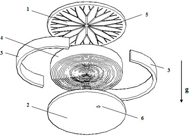
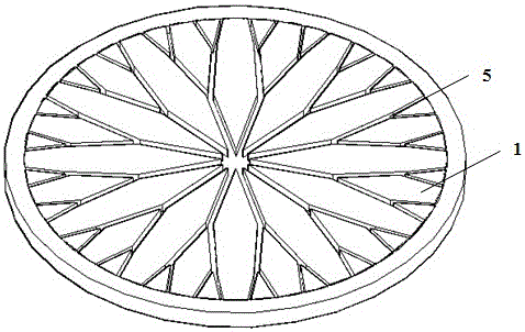
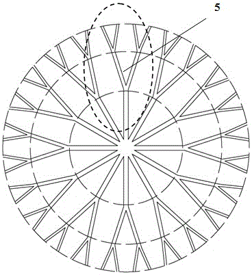
[0035] figure 1 Shown is a schematic diagram of the three-dimensional structure of a self-circulating gas-liquid two-phase flow phase-change heat exchanger working under anti-gravity conditions. It is a closed heat exchanger composed of an evaporation plate 1, a condensation plate 2, an annular wall surface 3 and a capillary cavity. The capillary cavity is composed of a liquid-absorbing core 4 and a gas-liquid two-phase working fluid. The evaporating plate 1 and the condensing plate 2 are connected by an annular wall 3; the liquid-absorbing core 4 is a gradient liquid-absorbing core rolled from wire mesh with different apertures, and the gradient liquid-absorbing core is covered with capillary chambers; the evaporating plate 1 is equipped with The groove 5, the groove 5 is a stepped bifurcated groove extending radially outward from the center. In add...


PUM


Abstract

The invention discloses a self-circulation gas-liquid two-phase flow phase change heat exchanger. The self-circulation gas-liquid two-phase flow phase change heat exchanger comprises an evaporation plate, a condensation plate, and a wall surface positioned between the evaporation plate and the condensation plate; and a capillary cavity is formed in the wall surface, and is provided with a liquid sucking core and a working medium positioned in the liquid sucking core and with gas and liquid two phases. The self-circulation gas-liquid two-phase flow phase change heat exchanger is characterized in that a groove structure is formed in the inner surface of the evaporation plate; grooves are gradient branched grooves outwards branched and extending in the radial direction from the center; the liquid sucking core is a gradient liquid sucking core with high capillary force in an axis area and low capillary force in a peripheral area; the axis area of the liquid sucking core is aligned to the center of the groove structure to form a main channel of a liquid working medium; and the peripheral area of the liquid sucking core is aligned to the branched grooves of the groove structure to form a main channel of a gaseous working medium. The heat exchanger can effectively improve circulation of gas and liquid working mediums under the condition of anti-gravity, improves the heat transfer performance, and provides guarantee for efficient and reliable operation of electronic devices.

Description

technical field [0001] The invention relates to a heat transfer device, in particular to a self-circulating gas-liquid two-phase flow with cascaded structure characteristics designed to improve the circulation of gas-liquid two-phase working medium and realize efficient and rapid heat transfer under anti-gravity conditions Phase change heat exchanger. Background technique [0002] Effective cooling of electronic components and devices has always been one of the main applications in the field of modern heat transfer. However, with the rapid development of technologies such as the electronic information industry and micro-electro-mechanical systems (MEMS), the development trend of miniaturization, high integration, and high power of electronic components has intensified. How to ensure that the heat in the chip is discharged in time under high heat flux density, so that its temperature can be controlled within the safe working range has become one of the key technologies to im...

Claims


Application Information

Patent Timeline
Patent Type & Authority Applications(China)
IPC IPC(8): F28D15/04
CPCF28D15/04
Inventor 徐德好张程宾张孟臣
Owner 南京艾科美热能科技有限公司
Why Eureka
Try Eureka