Heat exchange pipe and heat pump unit

A technology of heat exchange tubes and heat exchange structures, which is applied in the direction of heat sinks, refrigerators, refrigeration components, etc., and can solve the problems of high manufacturing costs of heat pump units

Inactive Publication Date: 2018-12-28
GREE ELECTRIC APPLIANCES INC OF ZHUHAI
View PDF7 Cites 4 Cited by
  • Summary
  • Abstract
  • Description
  • Claims
  • Application Information

AI Technical Summary

Problems solved by technology

[0005] The embodiment of the present invention provides a heat exchange tube and a heat pump unit to solve the technical problem of high manufacturing cost of the heat pump unit in the prior art

Method used


Image

  • Heat exchange pipe and heat pump unit
  • Heat exchange pipe and heat pump unit
  • Heat exchange pipe and heat pump unit

Examples


Embodiment Construction

[0025] In order to make the object, technical solution and advantages of the present invention clearer, the present invention will be described in further detail below in conjunction with the embodiments and accompanying drawings. Here, the exemplary embodiments and descriptions of the present invention are used to explain the present invention, but not to limit the present invention.

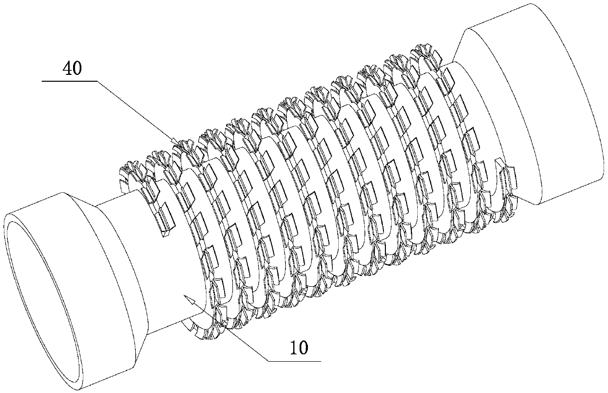
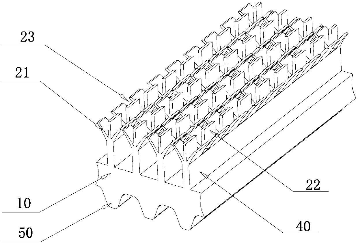
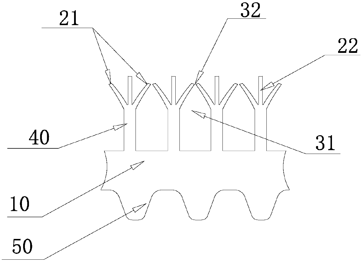
[0026] figure 1 An embodiment of the heat exchange tube of the present invention is shown, which includes a tube body 10 and fins 40 provided on the outer surface of the tube body 10 . A condensation heat exchange structure is formed on the fin 40 , and an evaporation heat exchange structure is formed between the fin 40 and the outer surface. The condensation heat exchange structure includes a fin platform heat exchange structure 21 , and the fin platform heat exchange structure 21 is formed on both sides of the top of the fin 40 .

[0027] Applying the technical solution of the present inven...


PUM


Abstract

The invention provides a heat exchange pipe and a heat pump unit. The heat exchange pipe comprises a pipe body and fins arranged on the outer surface of the pipe body. Condensation heat exchange structures are formed on the fins, and evaporation heat exchange structures are formed between the fins and the outer surface. The condensation heat exchange structures comprise fin table heat exchange structures which are formed on the two sides of the tops of the fins. The heat exchange pipe can be suitable for the refrigerating condition and the heating condition of the heat pump unit simultaneously, and thus the manufacturing cost of the heat pump unit is lowered.

Description

technical field [0001] The invention relates to the technical field of refrigeration, in particular to a heat exchange tube and a heat pump unit. Background technique [0002] The air source screw heat pump unit can cool in summer and heat in winter. The cooling and heating functions can be switched at any time according to needs. Its versatility is favored by the market, especially for medium-sized commercial buildings in hot summer and cold winter areas. widely used in. In the early stage, the structure of the evaporator used in the heat pump unit was mainly a dry evaporator, but the heat exchange efficiency of the dry evaporator was low. In recent years, the flooded evaporator and the falling film evaporator have high heat transfer efficiency and the energy efficiency of the unit It is widely used in heat pump units. When the flooded or falling film heat pump unit is in the cooling condition, the outside of the tube is a low-pressure saturated liquid refrigerant, and th...

Claims


Application Information

Patent Timeline
IPC IPC(8): F28F1/42F25B39/00
CPCF25B39/00F28F1/42F28F2215/10
Inventor 王宗信王丽岳清学杨旭峰胡海利
Owner GREE ELECTRIC APPLIANCES INC OF ZHUHAI
Why Eureka
Try Eureka