Environment-friendly waste gas treatment device

An exhaust gas treatment device and exhaust gas treatment technology are applied in combined devices, fixed filter elements, filter separation, etc., which can solve problems such as insufficient energy saving and environmental protection, single structure, and poor filtration and purification performance.

Inactive Publication Date: 2021-02-09
王永红
View PDF0 Cites 0 Cited by
  • Summary
  • Abstract
  • Description
  • Claims
  • Application Information

AI Technical Summary

Problems solved by technology

[0004] The existing exhaust gas treatment device has a single and traditional structure, poor filtration and purification performance, and the treatment process is not energy-saving and environmentally friendly. Innovative improvements to the structure are needed to overcome the shortcomings in current practical applications.

Method used


Image

  • Environment-friendly waste gas treatment device
  • Environment-friendly waste gas treatment device
  • Environment-friendly waste gas treatment device

Examples


Embodiment 1

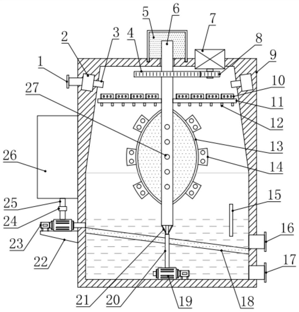
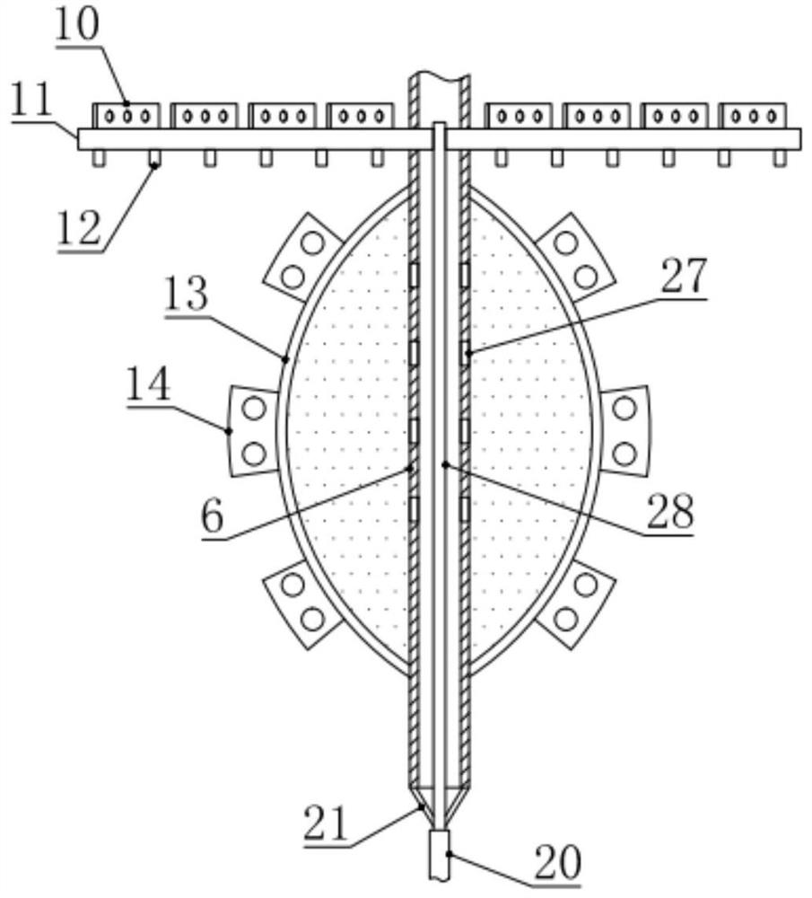
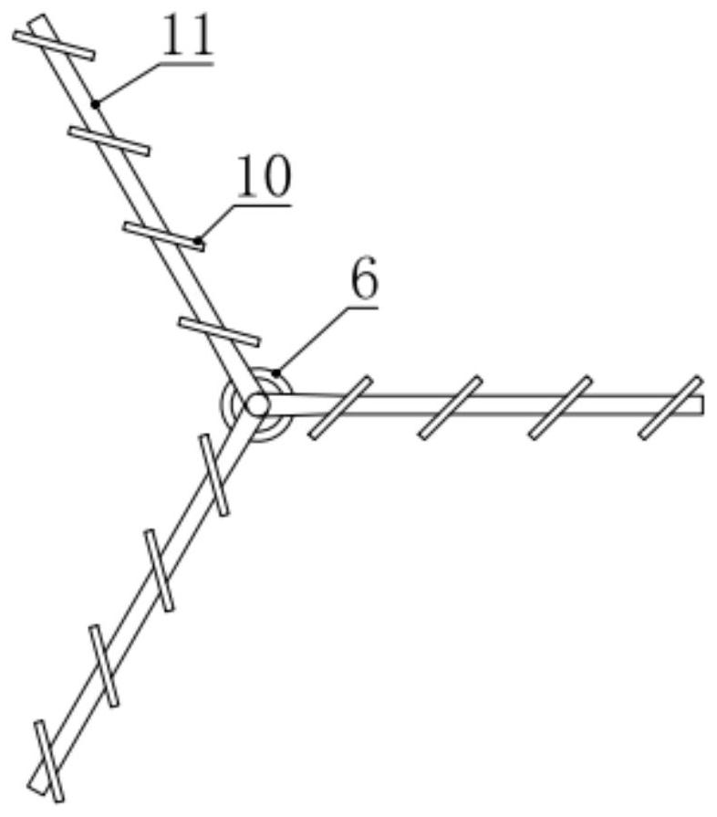
[0018] see Figure 1-2 , in the embodiment of the present invention, a waste gas treatment device for environmental protection includes a waste gas treatment box 9, a center pipe 6 is installed in the middle of the waste gas treatment box 9, and a center pipe 6 for driving the center pipe is also installed on the waste gas treatment box 9. 6 rotating drive components, the central pipe 6 in the exhaust gas treatment box 9 is equipped with a filter screen cylinder 13, and a number of second stirring blades 14 are installed on the outside of the filter screen cylinder 13, and the central pipe 6 in the filter screen cylinder 13 Several exhaust holes 27 are provided, and a plurality of spray pipes 11 are installed circumferentially on the central pipe 6 above the filter screen cylinder 13, and a plurality of atomizing nozzles 12 are installed on the lower side of the spray pipe 11. The upper side of the shower pipe 11 is equipped with a plurality of first stirring blades 10, and th...

Embodiment 2

[0021] see Figure 1-4 , the difference between this embodiment and embodiment 1 is:

[0022] In this example, if figure 1 and 2 As shown, the central pipe 6 is sealed and rotationally connected to the top of the exhaust gas treatment box 9, and the central pipe 6, the communication pipe 28 and the water delivery pipe 20 are coaxially arranged. In order to improve the structural stability of the communication pipe 28, the central pipe 6 The lower end is also provided with a plurality of diagonal struts 21 distributed circumferentially, the lower ends of the diagonal struts 21 are connected and fixed to the connecting pipe 28, and the connecting pipe 28 can be stably supported by the diagonal struts 21, which is beneficial to the remaining water in the central pipe 6. Discharge from the lower end of the central tube 6.

[0023] The driving assembly includes a driven gear 4, a servo motor 7 and a driving gear 8. The driven gear 4 is fixed on the center pipe 6 at the top of th...


PUM


Abstract

The invention relates to the field of waste gas treatment, in particular to an environment-friendly waste gas treatment device which comprises a waste gas treatment box, a central pipe is rotatably mounted in the middle of the waste gas treatment box, a filter screen cylinder is mounted on the central pipe, and a plurality of second stirring blades are mounted on the outer side of the filter screen cylinder. A plurality of spraying pipes are further circumferentially distributed and mounted on the central pipe above the filter screen cylinder, a plurality of atomizing nozzles are mounted on the lower sides of the spraying pipes, a plurality of first stirring blades are mounted on the upper sides of the spraying pipes, a communicating pipe communicating with the spraying pipes is arranged on the inner side of the central pipe, and the lower end of the communicating pipe rotatably communicates with a water conveying pipe. The lower end of the water conveying pipe is connected with a first water pump arranged at the bottom in the waste gas treatment box. The device is good in filtering and purifying performance, energy-saving and environment-friendly in treatment process and worthy ofpopularization.

Description

technical field [0001] The invention relates to the field of waste gas treatment, in particular to a waste gas treatment device for environmental protection. Background technique [0002] Exhaust gas refers to the poisonous and harmful gases emitted by human beings in the process of production and life, especially the generation of waste gas from chemical plants, steel plants, pharmaceutical factories, coking plants, oil refineries and human life. The exhaust gas has a strong smell. Seriously pollute the environment and affect human health. [0003] There are many types of pollutants in exhaust gas, their physical and chemical properties are very complex, and their toxicity is also different. The exhaust gas discharged from fuel combustion contains sulfur dioxide, nitrogen oxides, hydrocarbons, etc.; due to the different raw materials and processes used in industrial production, various harmful gases and solid wastes are discharged, containing various components such as hea...

Claims


Application Information

Patent Timeline
Patent Type & Authority Applications(China)
IPC IPC(8): B01D50/00B01D29/03
CPCB01D29/03B01D50/60
Inventor 王永红王丽珍
Owner 王永红
Why Eureka
Try Eureka