Check patentability & draft patents in minutes with Patsnap Eureka AI!

Scraping mechanism for production line

A production line and material scraping technology, which is applied in the direction of cleaning methods and tools, cleaning methods using tools, chemical instruments and methods, etc., can solve the problem that debris and dust cannot be cleaned in time, affect the operation effect of the production line, and have low precision of mechanical components, etc. problems, achieve good air quality, avoid direct stacking and external contact, and save processing time

Active Publication Date: 2021-09-21
CHONGQING TECH & BUSINESS UNIV
View PDF8 Cites 0 Cited by
  • Summary
  • Abstract
  • Description
  • Claims
  • Application Information

AI Technical Summary

Problems solved by technology

[0004] The present invention intends to provide a scraping mechanism for a production line to solve the problem that debris and dust will be generated during the operation of the existing production line, and the debris and dust cannot be cleaned in time, so they will accumulate. After a large amount of accumulation, It will affect the operation effect of the production line, resulting in the problem of low precision of the prepared mechanical components

Method used


Image

  • Scraping mechanism for production line
  • Scraping mechanism for production line
  • Scraping mechanism for production line

Examples


Embodiment 1

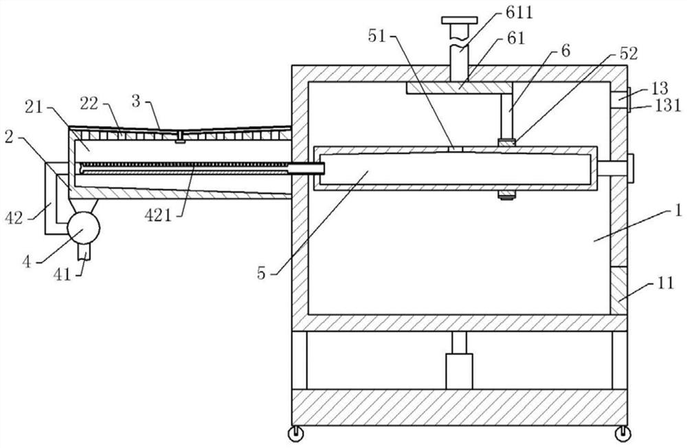
[0038] Scraping mechanism for production line, basically as attached figure 1 As shown, it includes a collection part and a scraping part. The collection part includes a collection box 1 and a collection plate 2 fixed on the left side wall of the collection box 1. The right bottom of the collection box 1 is provided with a discharge port, and the discharge port is provided with Sealing plug 11. The bottom of the collection box 1 is also provided with a base, and four corners of the bottom of the base are provided with moving wheels; The four corners of the upper surface of the base are also welded with telescopic rods, and the top of the telescopic rods is welded to the bottom of the collection box 1 .

[0039] The collecting plate 2 is provided with a material guiding channel 21, the right end of the material guiding channel 21 runs through the collecting plate 2, and the material guiding channel 21 is inclined downward from left to right; The surface is also provided with a ...

Embodiment 2

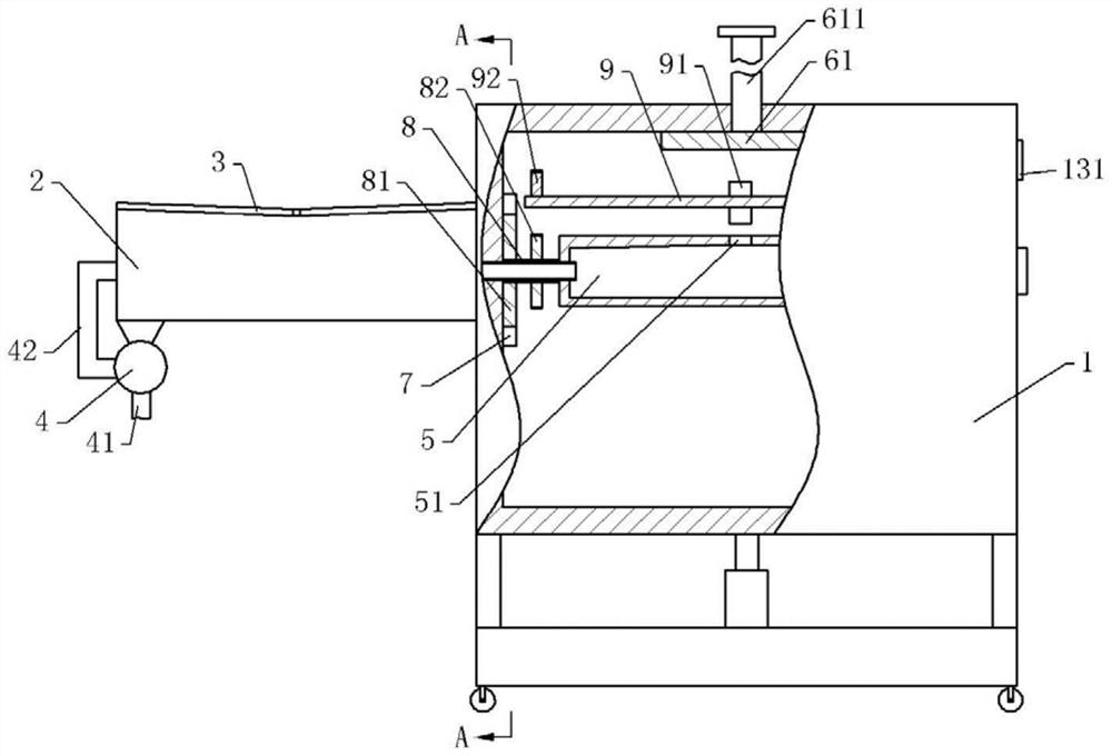
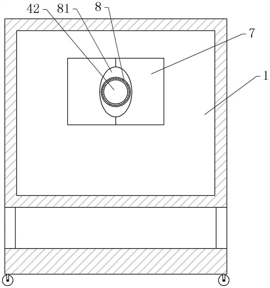
[0054] Embodiment 2 differs from Embodiment 1 only in that, as figure 2 Shown, in the present embodiment, also be provided with two baffles 7 that can close the collecting port, combine image 3 As shown, the inner wall of the collection box 1 is provided with two slide grooves respectively located on the left and right sides of the collection port, and the baffle plate 7 is provided with sliding blocks that cooperate with the slide grooves, so that the baffle plate 7 can be moved horizontally along the slide groove. slide. The opposite sides of the two baffle plates 7 are provided with gaps, and the splicing of the two gaps is oval; Springs are welded between the bottom and the bottom.

[0055] The diffusion section of the dust outlet pipe 42 is provided with a sleeve 8 coaxially with the dust outlet pipe 42, and the sleeve 8 is rotatably connected with the dust outlet pipe 42. The sleeve 8 is also coaxially fixed with an oval The driving block 81 is located in the notch,...


PUM


Abstract

The invention belongs to the technical field of equipment with a reciprocating scraper, and discloses a scraper mechanism for a production line, which includes a scraper part and a collection part. The collection part includes a collection box and a collection plate fixed on one side of the collection box. The collection plate There is a material guide channel inside, the top of the collecting plate is provided with a number of material guide holes connected with the material guide channel, and the side wall of the collection box is provided with a collection port connected with the material guide channel; the scraping part includes a vertically penetrating collection plate And the rotating shaft extending to the top of the collecting plate and the scraping rod fixed on the rotating shaft, the rotating shaft is rotatably connected with the collecting plate, the scraping rod is attached to the upper surface of the collecting plate, and the driving member for driving the rotating shaft to rotate is fixed on the collecting plate. The present invention solves the problem that the existing production line will produce debris and dust during operation, and the debris and dust cannot be cleaned in time, so they will accumulate. When a large amount of accumulation will affect the operation effect of the production line, resulting in the mechanical The problem of low accuracy of components.

Description

technical field [0001] The invention belongs to the technical field of equipment with a reciprocating scraper, and in particular relates to a scraper mechanism for a production line. Background technique [0002] In the production process of mechanical components, they are usually processed through multiple processing steps. With the continuous improvement of technology, a production line for processing mechanical components has emerged. By integrating the equipment required for each processing step into one production line, it can pass The automated machine system realizes the product process. [0003] The processing process of mechanical components is formed by turning, grinding, polishing and other steps of raw material blanks, and debris and dust will be generated in each step. After a long time of work, debris and dust will accumulate. When broken After a large amount of chips and dust accumulate, it will affect the operation of the production line; and after the dust ...

Claims


Application Information

Patent Timeline
Patent Type & Authority Patents(China)
IPC IPC(8): B08B15/00B08B1/04B08B13/00
CPCB08B15/00B08B13/00B08B1/165B08B1/32
Inventor 马斌陈希瑞夏洪均
Owner CHONGQING TECH & BUSINESS UNIV
Features
  • R&D
  • Intellectual Property
  • Life Sciences
  • Materials
  • Tech Scout
  • Unparalleled Data Quality
  • Higher Quality Content
  • 60% Fewer Hallucinations
Learn More