Double-station bidirectional die changing trolley

A double-station, mold trolley technology, applied in the field of mold changing vehicles, can solve the problem of changing molds for a piece of equipment, and achieve the effect of improving mold changing efficiency

Active Publication Date: 2021-02-09
武汉博莱恩智能装备有限公司
View PDF9 Cites 2 Cited by
  • Summary
  • Abstract
  • Description
  • Claims
  • Application Information

AI Technical Summary

Problems solved by technology

[0004] In view of this, it is necessary to provide a dual-station two-way mold changing trolley to solve the problem th

Method used


Image

  • Double-station bidirectional die changing trolley
  • Double-station bidirectional die changing trolley
  • Double-station bidirectional die changing trolley

Examples


Example Embodiment

[0021]The preferred embodiments of the present invention will be described below in detail with reference to the accompanying drawings. The accompanying drawings constitute a part of this application and are used together with the embodiments of the present invention to explain the principle of the present invention, and are not used to limit the scope of the present invention.
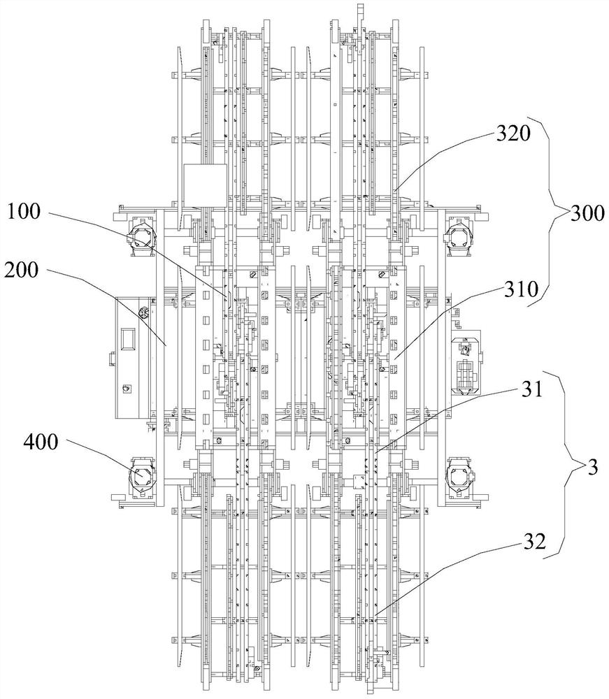
[0022]SeeFigure 1 to Figure 5, The dual-station two-way mold changing trolley includes four lifting push-pull mold changing machines 100, a vehicle body 200, four auxiliary guide rails 300, and a turning motor 400.

[0023]The bottom of the car body 200 is provided with wheels or tracks that facilitate the movement of the car body 200. Since the internal equipment layout of the factory is generally neat, there is generally a track between the two rows of equipment. The two rows of equipment are used to place the mold in the direction of the track. , The car body 200 can travel along the track and stop next to the...


PUM


Abstract

The invention relates to a double-station bidirectional die changing trolley. The double-station bidirectional die changing trolley comprises a trolley body, four lifting type push-pull die changing machines and four auxiliary guide rails, wherein the four auxiliary guide rails are arranged on the trolley body in parallel at intervals, the two ends of the auxiliary guide rails extend out of the trolley body, every two auxiliary guide rails form a set, every two lifting type push-pull die changing machines are arranged between every two sets of guide rails, and the two lifting type push-pull die changing machines face the two ends of the auxiliary guide rails correspondingly. Compared with the prior art, the double-station bidirectional die changing trolley is provided with the four liftingtype push-pull die changing machines, the two lifting type push-pull die changing machines face one side of the double-station bidirectional die changing trolley, the two lifting type push-pull die changing machines face the other side of the double-station bidirectional die changing trolley, dies can be changed for equipment located on the two sides of the double-station bidirectional die changing trolley at the same time, and the existing die changing efficiency can be doubled.

Description

technical field [0001] The invention relates to the technical field of mold changing vehicles, in particular to a dual-station bidirectional mold changing trolley. Background technique [0002] In the existing mechanical processing, more and more factories adopt machine tool processing methods to improve production efficiency and reduce scrap rate, so molds / tooling are widely used. However, the current mechanical processing plants generally do not only process one or several products, but manufacture or provide molds for processing and production according to customer needs. Since few customers' orders require machining plants to process and produce for several months, it is often necessary to change molds frequently to produce for different customers. [0003] Nowadays, conventional mold change generally adopts methods such as crane hoisting, forklift handling, and manual lifting platform, which seriously affects production efficiency and prolongs delivery cycle. However,...

Claims


Application Information

Patent Timeline
IPC IPC(8): B21D37/14B29C33/30
CPCB21D37/147B29C33/30
Inventor 曾科饶先杰
Owner 武汉博莱恩智能装备有限公司
Why Eureka
Try Eureka